
Collecting device for fine-grained silting sediments in modern lake

A collection device and sediment technology, which is applied in the field of sediment collection, can solve the problems of coarse-grained sediment mixing in the watershed, and achieve the effects of reducing floor space, reducing friction, and improving durability

Active Publication Date: 2021-07-02
JILIN UNIV
View PDF10 Cites 0 Cited by
  • Summary
  • Abstract
  • Description
  • Claims
  • Application Information

AI Technical Summary

Problems solved by technology

[0003] The purpose of the present invention is to provide a collection device for fine-grained silt deposits in modern lakes, to solve the technical problem in the prior art that coarse-grained sediments in the watershed are mixed into the sediment collection device

Method used


Image

  • Collecting device for fine-grained silting sediments in modern lake
  • Collecting device for fine-grained silting sediments in modern lake
  • Collecting device for fine-grained silting sediments in modern lake

Examples


Embodiment 2

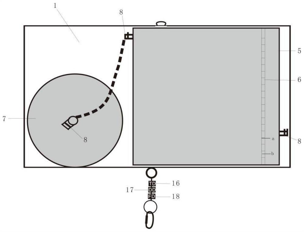
[0054] This implementation mode is regarded as a preferred embodiment of the present invention, and the specific structure is as follows Figure 1-5 As shown, it discloses the following improvements on the basis of Embodiment 1. An air chamber 5 is provided in the suspension chamber 1 , a water level limiter 6 is connected inside the air chamber 5 , and an air tank 7 is connected to one side of the air chamber 5 .

[0055] By setting the gas tank 7 and the gas cabin 5, the gas tank 7 and the gas cabin 5 are both cylindrical, and the volume ratio is between 3:5 and 4:5. The gas tank 7 is filled with N2, and the amount of N2 is smaller than that of the gas tank 7 air pressure, the water in the air chamber 5 can change the water level in the air chamber 5 through the air tank 7, thereby changing the weight of the suspension chamber 1 and the buoyancy in the water.

Embodiment 3

[0057] This implementation mode is regarded as a preferred embodiment of the present invention, and the specific structure is as follows Figure 1-5 As shown, it discloses the following improvement on the basis of Embodiment 2, the suspension cabin 1 is provided with a plurality of remote-controlled magnetic valves 8 .

[0058] By setting the remote control magnetic valve 8, it is convenient to control the lifting of the suspension cabin 1.

Embodiment 4

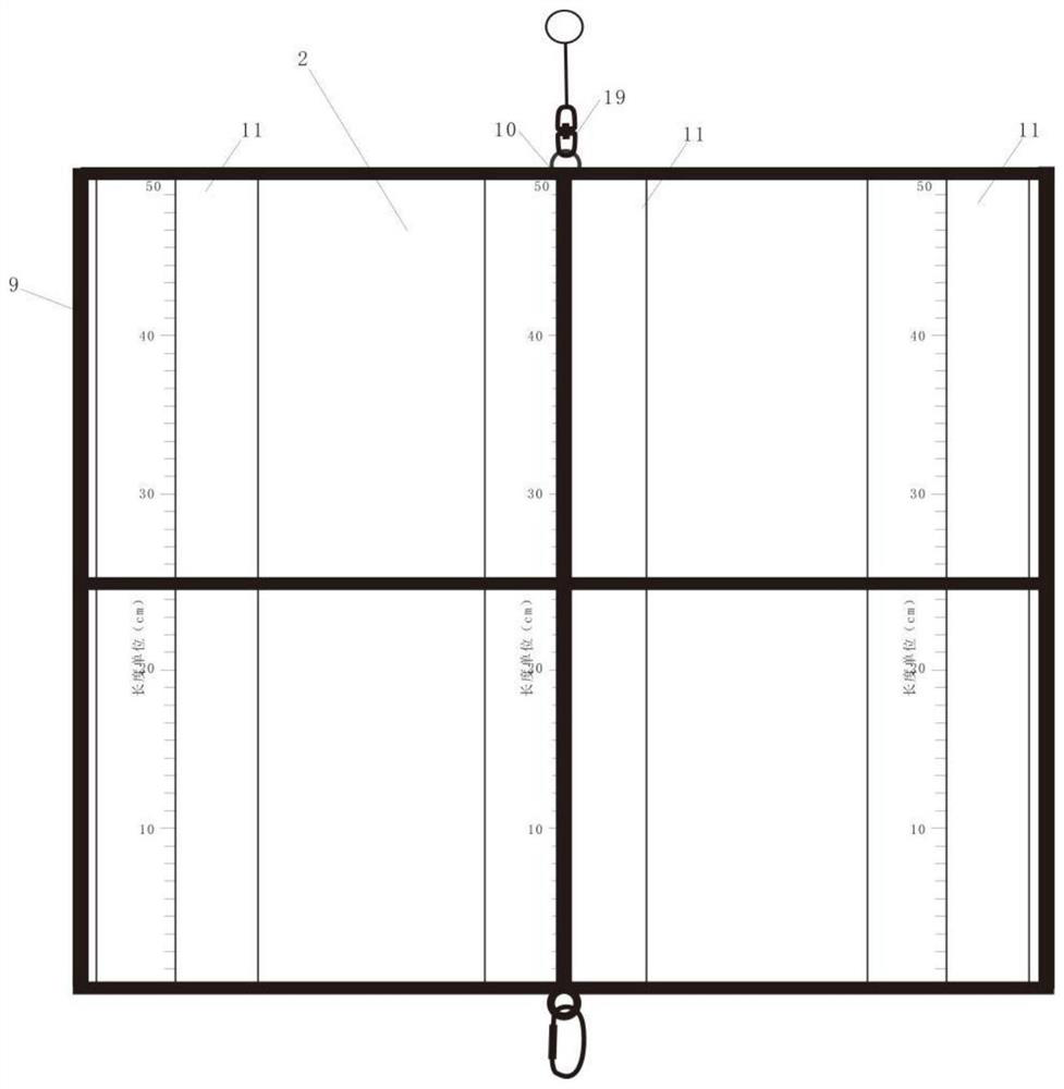
[0060] This implementation mode is regarded as a preferred embodiment of the present invention, and the specific structure is as follows Figure 1-5 As shown, it discloses the following improvements on the basis of Embodiment 3, the collector 2 includes a cylindrical collection frame 9, a cross support frame 10 is connected to the collection frame 9, and four collection cups 11 are fixedly connected to the collection frame 9 .

[0061] By setting the collection frame 9, the cross support frame 10 can support the external cylindrical frame to prevent the collection frame 9 from being deformed by the impact of external force, and the external cylindrical frame can effectively relieve the impact of the external force in the water and effectively protect the internal fixed collection cup 11 role.


PUM


Abstract

The invention discloses a collection device for fine-grained silt sediments in a modern lake, and belongs to the technical field of sediment collection. The device comprises a suspension cabin, the lower part of the suspension cabin is connected with a collector, the lower part of the collector is connected with a weight increasing component, one side of the suspension cabin is connected with an anchoring system. By arranging the suspension cabin, the position of the collector in water can be adjusted, the collector is guaranteed to be balanced and upright in water in cooperation with the weight increasing component, and coarse particles formed by underwater disturbance are prevented from being mixed in; and by arranging the collector and the anchoring system, a collecting frame can have high flexibility and collision resistance, the position of a collecting system can be fixed, real-time monitoring is achieved through a GPS positioner, and the singleness and stability of the source of silt falling and settling are guaranteed.

Description

technical field [0001] The invention belongs to the technical field of sediment collection, and in particular relates to a collection device for fine-grained sediment in modern lakes. Background technique [0002] "Considering the present and discussing the past" is an important idea in geological research, and it is a golden key to accurately understand the geological environment conditions in the past. Accurate reproduction of deposition rates is particularly critical during the study of lake fine-grained depositional environments and depositional dynamics. At present, the academic community mainly calculates the lake sedimentation rate through dating methods, and the dating error and the compaction of the sedimentary system itself bring great uncertainty to the deposition rate. The scientific and systematic one-year continuous sampling through the sediment collection device can obtain a relatively objective deposition rate under the current natural conditions, which can ...

Claims


Application Information

Patent Timeline
Patent Type & Authority Applications(China)
IPC IPC(8): B63C11/52B63G8/00B63G8/24G01N1/10G01D21/02
CPCB63C11/52B63G8/001B63G8/24G01N1/10G01D21/02B63G2008/002
Inventor 张新荣方石
Owner JILIN UNIV
Learn More