Eureka AIR delivers breakthrough ideas for toughest innovation challenges, trusted by R&D personnel around the world.

Video-based dynamic heart rate detection method

A detection method and heart rate technology, applied in the biometric mode based on physiological signals, measuring pulse rate/heart rate, diagnostic recording/measurement, etc., can solve problems such as discomfort, complicated operation, and inconvenience for the measurer, and achieve accurate and applicable detection Wide range, accuracy-enhancing effect

Pending Publication Date: 2021-01-08
SHANDONG IND TECH RES INST OF ZHEJIANG UNIV
View PDF6 Cites 2 Cited by
  • Summary
  • Abstract
  • Description
  • Claims
  • Application Information

AI Technical Summary

Problems solved by technology

[0005] At present, the traditional heart rate monitoring method is mainly contact type, but because of the complicated operation and the long-term contact with the human skin during the detection process, it will cause some inconvenience and discomfort to the measurer
Moreover, the general measurer needs to be in a static state when measuring the heart rate. When the device is in a state of motion, the recognition accuracy of the device will decrease, so it cannot help special groups such as ADHD patients, athletes, and motor vehicle drivers. The need to measure dynamic heart rate in the state of exercise
With the increase of health awareness, people pay more and more attention to various physiological indicators of their bodies, so the demand for dynamic heart rate detection increases, such as in dynamic scenes such as marathon long-distance running events and motor vehicle driving. Whether the heart rate of the subject is normal or not is likely to be related to their own life safety, and in a dynamic scene, the subject is often unable to continuously monitor the heart rate without contact with the human skin, which cannot meet the needs of real-time monitoring of dynamic heart rate

Method used


Image

  • Video-based dynamic heart rate detection method
  • Video-based dynamic heart rate detection method

Examples


Embodiment Construction

[0026] In order to enable those skilled in the art to better understand the solutions of the present invention, the technical solutions in the embodiments of the present invention will be clearly and completely described below in conjunction with the drawings in the embodiments of the present invention.

[0027] Such as Figure 1-2 Shown, a kind of dynamic heart rate detection method based on video, comprises the following steps:

[0028] S1: Video collection: use a common camera to continuously record the video of the face to be tested;

[0029] S2: Face recognition and tracking: detect and recognize the face data information in the video frame, calibrate the key points of the face, and keep track of the face;

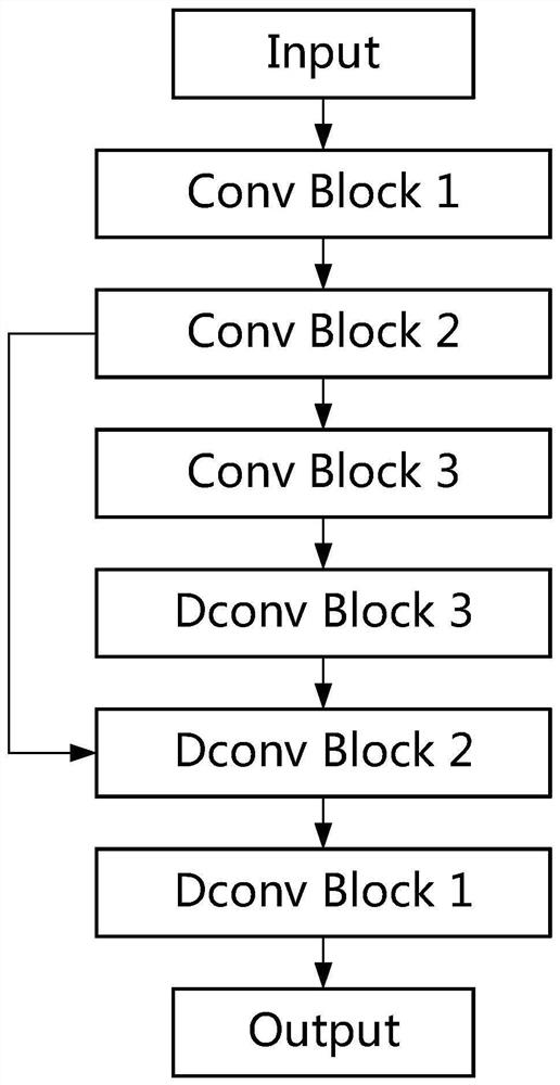
[0030] S3: Motion compensation: use the fully convolutional neural network to generate interpolated images for inter-frame motion compensation of video images;

[0031] S4: Illumination Compensation: By using the bilateral filter, the discontinuity in the illuminati...


PUM


Abstract

The invention discloses a video-based dynamic heart rate detection method. The method comprises the following steps: S1, video acquisition: carrying out continuous video recording on a human face needing to be tested by utilizing a common camera; s2, face recognition and tracking: detecting and recognizing face data information in the video frame, calibrating face key points, and keeping face tracking; s3, motion compensation: generating an interpolation image for inter-frame motion compensation of the video image by using a full convolutional neural network; s4, illumination compensation; S5,interested skin region signal extraction; s6, heart rate estimation: performing heart rate estimation by utilizing photoplethysmography, signal finding, artifact removal, spectral analysis and ECG-like signal reconstruction technologies; and S7, obtaining a heart rate detection signal. A non-skin-contact detection method is adopted, discomfort of a human body cannot be caused, and the detection accuracy is high.

Description

technical field [0001] The invention belongs to the technical field of heart rate detection, in particular to a video-based dynamic heart rate detection method. Background technique [0002] Heart rate is one of the most commonly measured parameters of the human body, and it is crucial to determine individual health, so heart rate monitoring plays an irreplaceable role in the monitoring of human health. [0003] Face tracking is to continue to capture information such as the position and size of the face in subsequent frames on the premise of detecting the face, including face recognition and face tracking technology. The traditional face recognition technology is mainly based on face recognition of visible light images, especially when the ambient light changes, the recognition effect will drop sharply, and there are still problems such as object occlusion and large differences between side faces and front faces. Traditional face tracking is based on this, and the natural ...

Claims


Application Information

Patent Timeline
IPC IPC(8): G06K9/00G06K9/32G06K9/62G06N3/04A61B5/024A61B5/0245
CPCA61B5/024A61B5/0245G06V40/16G06V40/161G06V40/171G06V40/10G06V40/15G06V10/25G06N3/048G06N3/045G06F18/2134
Inventor 吴健陈潇俊杨文韬
Owner SHANDONG IND TECH RES INST OF ZHEJIANG UNIV
Why Eureka
Eureka Blog
Learn More