Casting electric furnace dust collecting device

A technology of dust collection device and electric furnace, which is applied in combined devices, furnaces, furnace components, etc., can solve the problems of poor dust collection effect, waste of heat, and inability to collect heat, so as to avoid waste of heat, improve the utilization rate of heat, and improve efficiency effect

Inactive Publication Date: 2021-01-12
芜湖久弘重工股份有限公司
View PDF12 Cites 0 Cited by
  • Summary
  • Abstract
  • Description
  • Claims
  • Application Information

AI Technical Summary

Problems solved by technology

[0005] Aiming at the deficiencies of the prior art, the present invention provides a casting electric furnace dust collection device, which can make the dust collection device have the function of waste heat recovery, avoid heat waste, improve the utilization rate of heat of the device at the same time, and can improve the heating efficiency of the casting electric furnace. The efficiency of the material can also effectively improve the dust collection effect of the dust collection device, avoid fine dust from polluting the environment, improve the environmental protection performance of the dust collection device of the foundry electric furnace, and solve the problem that a large amount of heat will flow out when the dust of the foundry electric furnace is released. , but the existing dust collection device cannot collect heat and cause waste of heat, which affects the heat utilization rate of the device, and the dust collection device of the casting electric furnace is still poor and has the problem of poor dust collection effect

Method used


Image

  • Casting electric furnace dust collecting device
  • Casting electric furnace dust collecting device
  • Casting electric furnace dust collecting device

Examples


Embodiment Construction

[0025] The technical solutions in the embodiments of the present invention will be clearly and completely described below. Obviously, the described embodiments are only some of the embodiments of the present invention, but not all of them. Based on the embodiments of the present invention, all other embodiments obtained by persons of ordinary skill in the art without making creative efforts belong to the protection scope of the present invention.

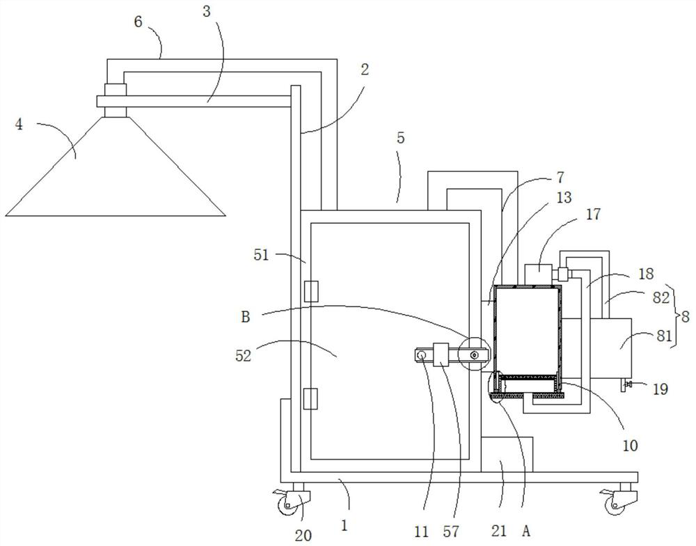
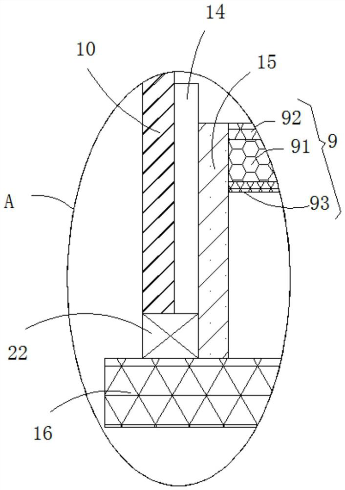
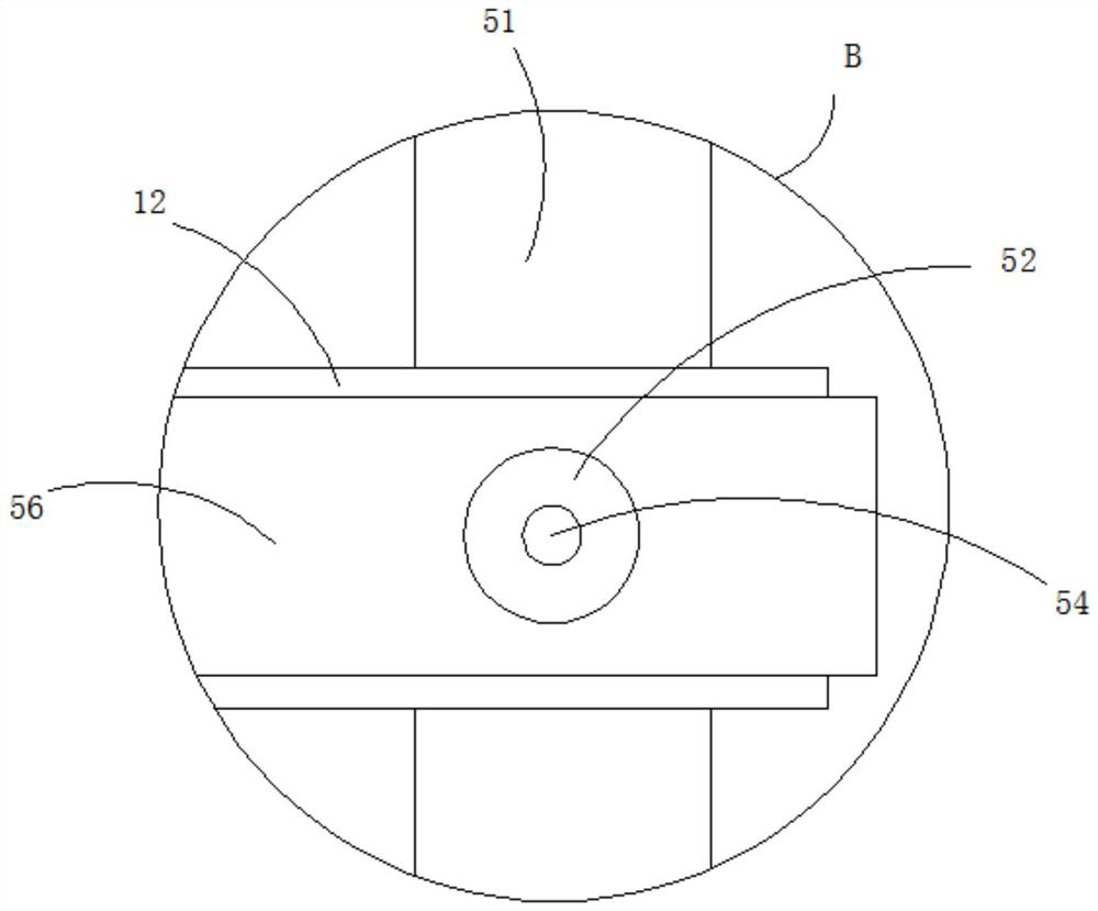
[0026] see Figure 1-4 , a casting electric furnace dust collection device, comprising a bottom plate 1, the upper surface of the bottom plate 1 is fixedly connected with a support plate 2, the side wall of the support plate 2 is fixedly connected with a fixed frame 3, and the inner wall of the fixed frame 3 is fixedly connected with a dust collection cover 4 , the upper surface of the bottom plate 1 is fixedly connected to the preheating mechanism 5, and the top end of the dust collecting hood 4 is fixedly communicated with a conve...


PUM


Abstract

The invention relates to the technical field of dust collecting equipment, and discloses a casting electric furnace dust collecting device, which comprises a bottom plate. A supporting plate is fixedly connected to the upper surface of the bottom plate, a fixing frame is fixedly connected to the side wall of the supporting plate, a dust collecting cover is fixedly connected to the inner wall of the fixing frame, a preheating mechanism is fixedly connected to the upper surface of the bottom plate, the top end of the dust collecting cover fixedly communicates with a conveying pipe, the bottom end of the conveying pipe fixedly communicates with the outer wall of the bottom end of the preheating mechanism, the upper surface of the preheating mechanism fixedly communicates with a guide pipe, the bottom end of the guide pipe fixedly communicates with a collecting box, and the outer wall of the collecting box is fixedly connected with a connecting block. According to the casting electric furnace dust collecting device, the dust collecting device can have the waste heat recovery function, heat waste is avoided, meanwhile, the heat utilization rate of the device is increased, the material heating efficiency of a casting electric furnace can be improved, the dust collecting effect of the dust collecting device can be effectively improved, fine dust is prevented from polluting the environment, and the environment-friendly performance of the casting electric furnace dust collecting device is improved.

Description

technical field [0001] The invention relates to the technical field of dust collection equipment, in particular to a dust collection device for a foundry electric furnace. Background technique [0002] At present, a large number of metal cutting processes are carried out in the production process of the machinery industry, which produces a large amount of metal waste. If these wastes are discarded, it will not only waste resources, but also seriously pollute the environment. Therefore, these metal wastes are recycled. , After processing, returning to the furnace for smelting is an effective treatment method. Since metal waste contains more impurities during the smelting process, a large amount of fine dust is prone to appear during the heating process. [0003] At present, when the casting electric furnace dust floats out, a large amount of heat will flow out, but the existing dust collection device cannot collect heat and cause heat waste, which affects the heat utilization...

Claims


Application Information

Patent Timeline
IPC IPC(8): B01D50/00F27D17/00
CPCF27D17/004F27D17/008B01D50/60Y02P10/25
Inventor 章国文俞胜宏
Owner 芜湖久弘重工股份有限公司
Why Eureka
Try Eureka