Washing machine roller reinforcing rod component automatic welding production line and control method

A washing machine drum, automatic welding technology, applied in welding equipment, welding equipment, welding accessories and other directions, can solve the problems of product scrap, difficult positioning process, etc., to reduce operating intensity, save manpower, improve welding reliability and welding accuracy. Effect

Active Publication Date: 2021-01-12
佛山市顺德区志创翔鸿实业有限公司
View PDF6 Cites 1 Cited by
  • Summary
  • Abstract
  • Description
  • Claims
  • Application Information

AI Technical Summary

Problems solved by technology

[0003] The reinforcing rod assembly includes a reinforcing rod and a fixed piece, and the reinforcing rod and the fixed piece are fixedly connected by welding to form an integral structure. In the prior art, the fixing piece and one end of the reinforcing rod are pre-connected manually, and then manually The two are welded and fixed, but because the reinforcing rod is a cylindrical structure, the positioning process is more difficult, and the connecting position of the reinforcing rod and the fixed piece must follow strict position dimensions, which puts higher technological requirements on the operator and is easy to cause Product scrap due to spar assembly not meeting dimensions

Method used


Image

  • Washing machine roller reinforcing rod component automatic welding production line and control method
  • Washing machine roller reinforcing rod component automatic welding production line and control method
  • Washing machine roller reinforcing rod component automatic welding production line and control method

Examples


Embodiment Construction

[0032] The following will clearly and completely describe the technical solutions in the embodiments of the present invention with reference to the accompanying drawings in the embodiments of the present invention. Obviously, the described embodiments are only part of the embodiments of the present invention, not all of them. Based on the embodiments of the present invention, all other embodiments obtained by persons of ordinary skill in the art without creative efforts fall within the protection scope of the present invention.

[0033] It should be noted that if there is a directional indication (such as up, down, left, right, front, back...) in the embodiment of the present invention, the directional indication is only used to explain the position in a certain posture (as shown in the accompanying drawing). If the specific posture changes, the directional indication will also change accordingly.

[0034] In addition, if there are descriptions involving "first", "second" and ...


PUM


Abstract

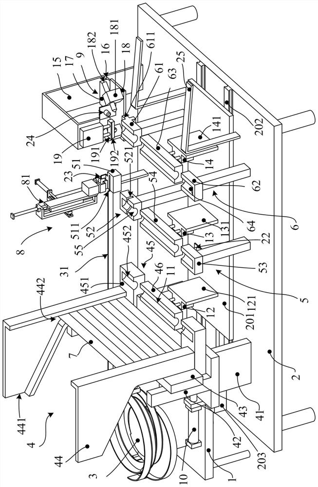
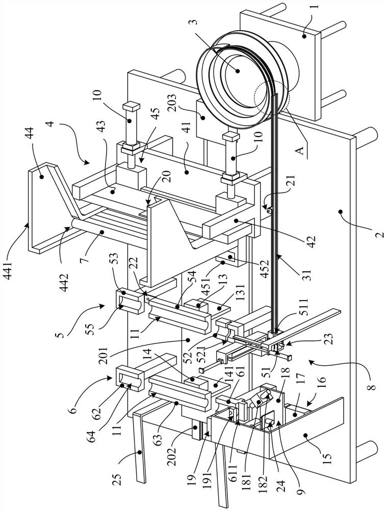
The invention discloses a washing machine roller reinforcing rod component automatic welding production line. The washing machine roller reinforcing rod component automatic welding production line comprises a vibration disc mounting base and an equipment mounting base; a vibration disc is arranged on the top surface of the vibration disc mounting base; a material receiving and conveying mechanism,a component pre-assembling mechanism and a component welding mechanism are sequentially arranged on the top surface of the equipment mounting base; the material receiving and conveying mechanism receives materials and sequentially conveys different reinforcing rods; a mechanical arm arranged at the side part of the component pre-assembling mechanism clamps and conveys fixing pieces conveyed by the vibration disc; the component pre-assembling mechanism receives the reinforcing rods and then is matched with the mechanical arm to position and pre-assemble the reinforcing rods and the fixing pieces; the pre-assembled reinforcing rod component is transferred to the component welding mechanism; and then the reinforcing rods and the fixing pieces are fixedly connected through welding. The invention further discloses a control method using the washing machine roller reinforcing rod component automatic welding production line. Compared with the prior art, the technical scheme of the washing machine roller reinforcing rod component automatic welding production line has the advantages of automatic control and the like, and can reduce the operation intensity, reduce the product rejection rateand improve the enterprise product benefit.

Description

technical field [0001] The invention relates to the technical field of drum washing machine reinforcement rod welding, in particular to an automatic welding production line and control method for a washing machine drum reinforcement rod assembly. Background technique [0002] A drum washing machine usually has a drum for washing clothes, and since the horizontally arranged drum is in the process of washing clothes, the water body and clothes are located in the lower part of the drum, which will cause a large centrifugal force when the drum rotates at a high speed , so in order to improve the structural strength of the drum, usually a reinforcing rod assembly is connected to the drum. [0003] The reinforcing rod assembly includes a reinforcing rod and a fixed piece, and the reinforcing rod and the fixed piece are fixedly connected by welding to form an integral structure. In the prior art, the fixing piece and one end of the reinforcing rod are pre-connected manually, and th...

Claims


Application Information

Patent Timeline
Patent Type & Authority Applications(China)
IPC IPC(8): B23K9/00B23K9/32B23K37/04
CPCB23K9/00B23K9/32B23K37/0443
Inventor 张镇栋谈引军
Owner 佛山市顺德区志创翔鸿实业有限公司
Why Eureka
Try Eureka