A composite sealing device on the side of a sintering machine

A sealing device and composite technology, which is applied in the field of iron ore sintering, can solve the problems of inability to guarantee safety, obscure structure and principle, complex structure and principle, etc., to improve side air leakage, and the principle is easy to understand , the effect of simple structure

Active Publication Date: 2021-10-08
临沂玫德庚辰金属材料有限公司
View PDF7 Cites 0 Cited by
  • Summary
  • Abstract
  • Description
  • Claims
  • Application Information

AI Technical Summary

Problems solved by technology

[0004] Some of the current sintering machine sealing devices are relatively complex in structure and principle, and some are not complicated in structure and principle but obscure. Whether the sealing method can produce beneficial effects needs to be further explored. Therefore, some large companies , Enterprises and factories dare not apply it in large quantities to practical production. The final result is that the sealing device can only stay in theory with a good sealing effect, and the feasibility of actual production practice is questionable, and even if it is true in actual production In the sense of achieving a low air leakage rate, but there is no guarantee that there will be no safety problems and subsequent air leakage problems

Method used


Image

  • A composite sealing device on the side of a sintering machine
  • A composite sealing device on the side of a sintering machine
  • A composite sealing device on the side of a sintering machine

Examples


Embodiment Construction

[0019] In order to more clearly explain the technical solutions of the present invention or the prior art, the drawings need to be used in the embodiments or prior art description will be described, and the accompanying drawings will be described below. Some embodiments of the invention, for those of ordinary skill in the art, other drawings can be obtained in accordance with these figures without paying creative labor.

[0020] It should be noted that in the description of the present invention, it is to be noted that the terms "upper", "lower", "top", "bottom", "one side", "other side", "left", " Right "or the like or positional relationship is based on the orientation or positional relationship shown in the drawings, but is intended to facilitate the description of the present invention and simplified description, rather than means a particular orientation, and operate.

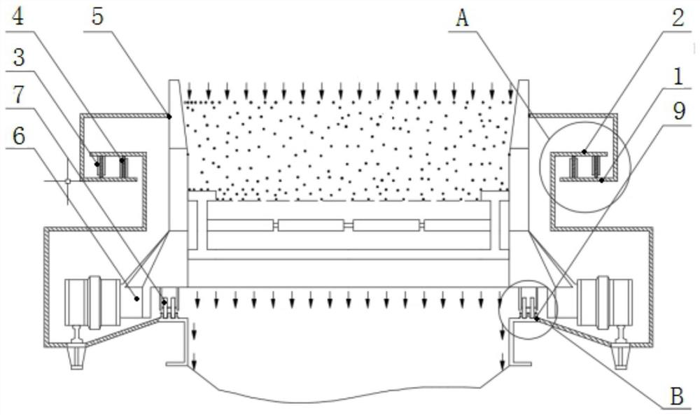
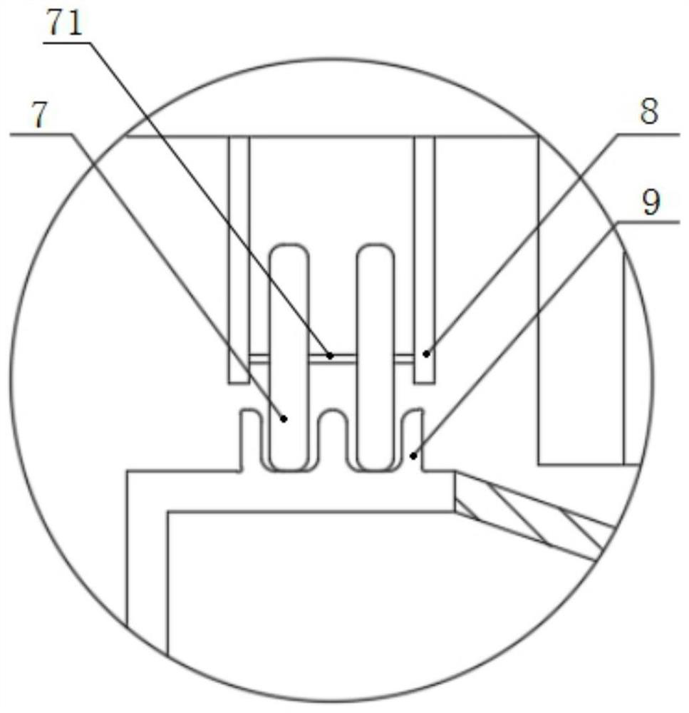
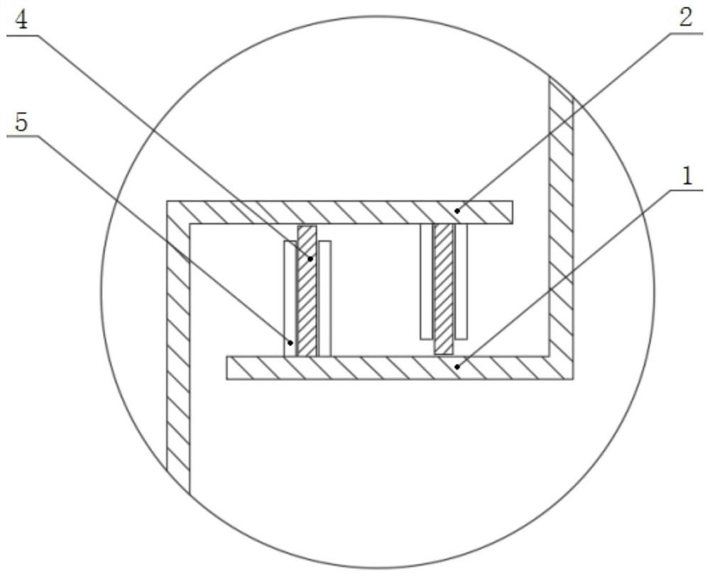
[0021] See Figure 1 to 3 The specific structure of one embodiment of a sintering machine side composite sea...


PUM


Abstract

The invention relates to a side compound sealing device of a sintering machine, which includes a side sealing assembly: the assembly includes an upper sealing cover plate, a lower sealing cover plate, a high-strength magnet, flexible rubber and a flexible rubber panel; and a roller guide assembly; the The assembly includes rollers, roller support plates and roller tracks; the roller support plates are fixedly connected in pairs to the left and right sides of the bottom of the trolley, and the rollers are respectively rotatably connected between each pair of roller support plates, and the roller tracks correspond to It is arranged at the bottom of the roller, and one end of the roller track is fixedly connected to the side of the trolley, and the other end is fixedly connected to one side of the bottom end of the lower sealing cover plate. During the sintering process, the negative pressure of the bellows is used to make the flexible rubber contact with the upper and lower sealing cover plates to form a sealing wall, and the rollers are used to replace the original side slideway device at the bottom of the trolley, so that the sliding seal becomes a rolling seal, which effectively reduces the contact between the trolley and the sliding It also has a certain guiding effect to reduce the air leakage caused by the deviation of the trolley.

Description

Technical field [0001] The present invention relates to the field of iron ore sintering techniques, and more particularly to a sintering machine side composite sealing device. Background technique [0002] Metallurgical technology has a long history of development, from the stone era to the subsequent bronze era, and then go to the large-scale development of modern steel smelting. History of human development combines the development history of metallurgy. Today, our human food and clothing is inseparable from steel, iron and other metals, and metallurgical has become an important member of industrial production. The sintering process is the pre-treatment process of metallurgy. The sintering process should be carried out normally, in order to lay a solid foundation for subsequent metallurgical processes. However, existing sintering techniques, including the sintering process of the tape sintering machine and the cooled sintering machine, there is a problem that cannot be ignored ...

Claims


Application Information

Patent Timeline
Patent Type & Authority Patents(China)
IPC IPC(8): F27B21/08F27D99/00
CPCF27B21/00F27D99/0076F27M2003/04
Inventor 任素波李忠阳何娜张星
Owner 临沂玫德庚辰金属材料有限公司
Why Eureka
Try Eureka