Switch and protection circuit for exoskeleton robot

An exoskeleton robot and protection circuit technology, applied in safety/protection circuits, protection for undervoltage or no voltage response, circuit devices, etc., can solve problems such as low safety, large size, and sparking phenomenon, and achieve Flexible switch selection, flexible control methods, and the effect of reducing the size of the switch

Active Publication Date: 2021-01-12
BEIJING RES INST OF PRECISE MECHATRONICS CONTROLS
View PDF6 Cites 0 Cited by
  • Summary
  • Abstract
  • Description
  • Claims
  • Application Information

AI Technical Summary

Problems solved by technology

The disadvantage of this method is that because the switch is placed on the busbar, the instantaneous current is large, and sparking is likely to occur, and in order to pass a large enough current, this type of switch is usually large in size, which is not enough for portable equipment Optimized, the environmental adaptability to waterproof and dustproof is also poor
[0004]At the same time, the current electrical system of the exoskeleton is powered on by the bus, and all subsystems are charged, which is less safe, and the power motor and the power motor cannot be controlled by the controller. The power used by the drive part is powered on and off
When there is a problem with the power motor and the drive part, the software cannot control its power failure
[0005]The power consumption of the power motor is large. When the voltage is low, if the power motor continues to output torque, it is easy to cause the battery to be over-discharged. If there is no hardware under-voltage protection circuit, the battery may be damaged due to over-discharge, affecting its service life
[0006] In order to solve the above problems, the present invention proposes an innovative scheme for switches and protection circuits for exoskeleton robots, which realizes weak current main switches, power electric software switches, Functions such as power under-voltage protection can significantly improve the safety and reliability of the exoskeleton electrical system, and ensure that its cycle life will not be significantly reduced due to battery over-discharge

Method used


Image

  • Switch and protection circuit for exoskeleton robot

Examples


Embodiment Construction

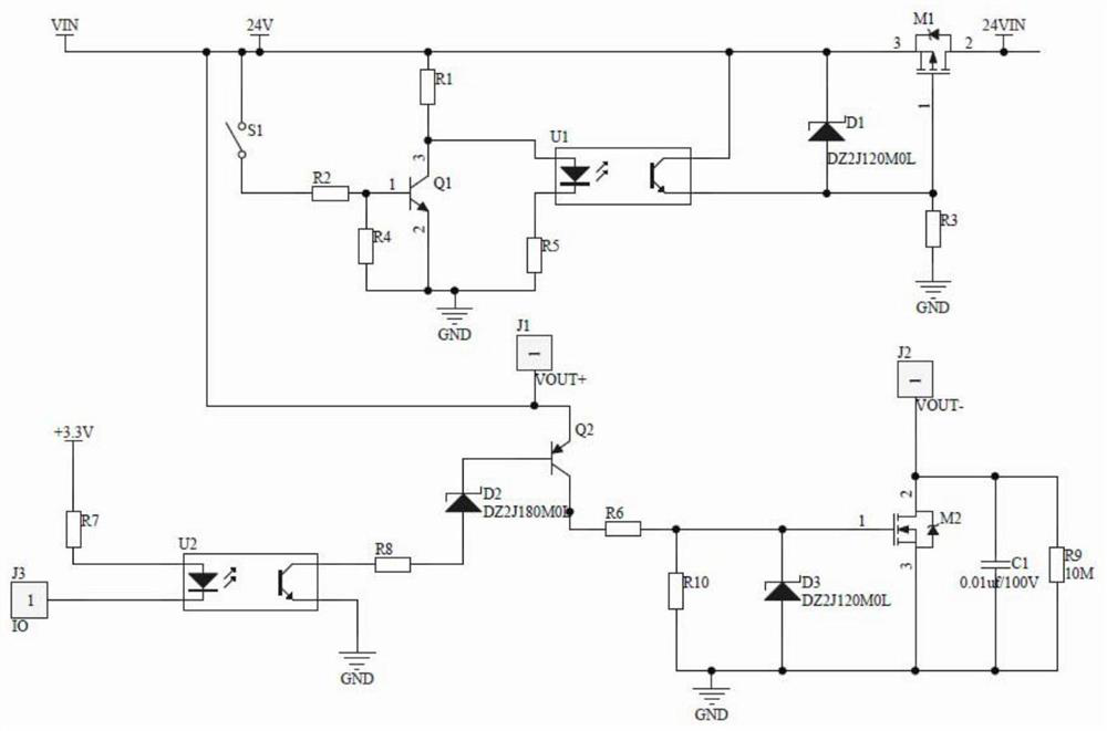
[0019] The invention relates to a switch and protection circuit for an exoskeleton robot, including a control electric switch circuit, a power electric switch circuit and a power electric undervoltage protection circuit.

[0020] After the input voltage is connected, it is divided into two circuits, one for the control chip, low-power step-down power supply and other low-power control electrical parts, and the other for exoskeleton motors, drivers and other high-power electrical equipment powered by. The switch circuit of the control power realizes the power-on or power-off of the control power through the closing or opening of the external button switch. The power electricity reaches the output interface after passing through the power electric switch circuit and the undervoltage protection circuit, and supplies power for the power equipment of the external driver. The power switch circuit can control the closing or opening of the switch by sending high and low level signals...


PUM


Abstract

The invention relates to a switch and a protection circuit, in particular to a switch and a protection circuit for an exoskeleton robot. The circuit comprises a first switch S1, a first resistor R1, asecond resistor R2, a third resistor R3, a fourth resistor R4, a fifth resistor R5, a first optocoupler U1, an NPN type first triode Q1, a first voltage stabilizing diode D1 and a P type first MOS tube M1; a seventh resistor R7, a second optical coupler U2, an eighth resistor R8, a second voltage stabilizing diode D2, a PNP type second triode Q2, a sixth resistor R6, a tenth resistor R10, a thirdvoltage stabilizing diode D3, an N type second MOS tube M2, a first capacitor C1 and a ninth resistor R9. The invention aims to solve the problem that the overcurrent of a main switch does not exceed50mA, and power-on or power-off of power can be controlled through an IO port of a control chip. Another technical problem to be solved by the invention is to provide an under-voltage turn-off circuit which can prevent an external power supply from over-discharging when the input voltage is too low.

Description

technical field [0001] The invention relates to a switch and a protection circuit, in particular to a switch and a protection circuit for an exoskeleton robot. Background technique [0002] As a wearable smart device, the exoskeleton system needs to ensure the absolute safety of the wearer, and it needs to work stably and reliably during the assisting process, and has a sufficient cycle life. Therefore, the exoskeleton system has high requirements on the safety, reliability and cycle life of its electrical system, and more protection measures are needed to meet the practical requirements. [0003] Existing exoskeleton electrical systems mostly use buttons or rocker switches that are large in size and capable of passing all bus currents and are connected in series on the bus as the main switch of the system. The disadvantage of this method is that because the switch is placed on the busbar, the instantaneous current is large, and sparking is likely to occur, and in order to ...

Claims


Application Information

Patent Timeline
Patent Type & Authority Applications(China)
IPC IPC(8): H02H3/24H02J7/00
CPCH02H3/24H02J7/00306
Inventor 刘家伦尹业成闫国栋张礼策孟令环
Owner BEIJING RES INST OF PRECISE MECHATRONICS CONTROLS
Why Eureka
Try Eureka