
Detection system based on time division type coaxial illumination imaging and sorting machine

A detection system and imaging technology, used in sorting, measuring devices, analyzing materials, etc., can solve problems such as increasing the contrast between defects and backgrounds, and achieve the effect of increasing the contrast between defects and backgrounds, and reducing missed or false detections.

Pending Publication Date: 2021-01-15
CHINA HEFEI TAIHE OPTOELECTRONICS TECH
View PDF0 Cites 2 Cited by
  • Summary
  • Abstract
  • Description
  • Claims
  • Application Information

AI Technical Summary

Problems solved by technology

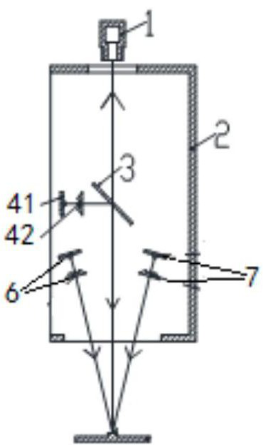
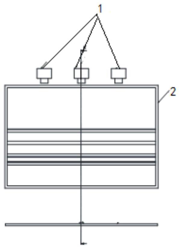
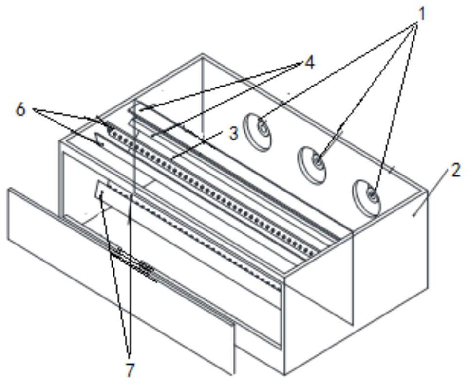
[0003] The invention discloses a detection system based on time-sharing coaxial illumination imaging, which solves the problem that the existing detection system is prone to missed detection and false detection when the surface is smooth and mirror reflection is easy to occur, and multiple groups of different angles are collected at the same time The image data system under illumination increases the contrast between defects and the background, greatly reducing missed or false detections caused by the randomness of the surface defects of the object to be tested

Method used


Image

  • Detection system based on time division type coaxial illumination imaging and sorting machine
  • Detection system based on time division type coaxial illumination imaging and sorting machine
  • Detection system based on time division type coaxial illumination imaging and sorting machine

Examples


Embodiment Construction

[0024] Embodiments of the present invention are described in detail below, examples of which are shown in the drawings, wherein the same or similar reference numerals designate the same or similar elements or elements having the same or similar functions throughout. The embodiments described below by referring to the figures are exemplary only for explaining the present invention and should not be construed as limiting the present invention.

[0025] Embodiments of the present invention will be described in detail below in conjunction with the accompanying drawings.

[0026] In the coaxial lighting technology, the light emitted by the LED white light source is shaped and concentrated by the cylindrical lens, and is emitted from the exit surface of the cylindrical lens in a manner close to parallel light. The parallel light enters the half-transparent mirror at an angle of 45°, and the incident light The angle between the normal line and the normal line is 45°, and the outgoing...


PUM


Abstract

The invention provides a detection system based on time division type coaxial illumination imaging and a sorting machine. The detection system comprises an image acquisition unit, a shading body, a semi-transparent semi-reflective spectroscope, a plurality of light source modules and a light source module drive unit. The image acquisition unit is used for acquiring product images. The shading bodyis a matte metal box body subjected to black spray treatment. The mirror surface of the beam splitter is plated with an optical coating with the reflectivity and transmissivity both being 50%, and the spectroscope is used for changing the propagation direction of emergent light of the light source modules and transmitting reflected light reflected by the surface of a to-be-detected object. The multiple light source modules are used for providing time division type light sources. The light source module driving unit outputs a pulse width modulation signal to drive the multiple light source modules, and each light source module is respectively lightened once in each clock period. In this way, the problem that when an existing detection system detects the to-be-detected object with a smoothsurface, missing detection and false detection are prone to happen since the smooth surface is prone to generate specular reflection is solved; and meanwhile the detection system based on time division type coaxial illumination imaging system acquires multiple groups of image data under illumination at different angles, the contrast ratio of defects and backgrounds is increased, and missing detection and false detection caused by randomness of surface defects of the to-be-detected object is greatly reduced.

Description

technical field [0001] The invention relates to the technical field of machine vision detection, in particular to a detection system suitable for time-sharing coaxial illumination imaging of objects prone to specular reflection. Background technique [0002] Machine vision inspection technology uses different light sources, cameras, signal processing systems and rejection systems, and is showing its talents in various industries. The basic principles of different machine vision inspection systems are similar, that is, light sources of different wavelength bands are used to illuminate the object to be tested, and the reflected light or transmitted light of the object to be measured is imaged on the camera sensor of the selected waveband through the selected lens, and the camera will collect The data is sent to the data processing system through analog-to-digital conversion. The processing system marks the targets that meet or fail the conditions through the set judgment algor...

Claims


Application Information

Patent Timeline
Patent Type & Authority Applications(China)
IPC IPC(8): B07C5/34B07C5/36G01N21/88
CPCB07C5/34B07C5/366G01N21/8806G01N2021/8835
Inventor 胡家鑫汪洪波桑浩石江涛
Owner CHINA HEFEI TAIHE OPTOELECTRONICS TECH
Learn More