
Automatic splined hub machining equipment with function of integrally forming tooth profile

A technology for processing equipment and spline hubs, which is applied in the field of automatic processing equipment for spline hubs, and can solve problems such as low efficiency, high processing costs, and long processing time for a single piece

Inactive Publication Date: 2021-01-15
东莞市帕特慕可科技有限公司
View PDF0 Cites 3 Cited by
  • Summary
  • Abstract
  • Description
  • Claims
  • Application Information

AI Technical Summary

Problems solved by technology

[0003] The existing spline hub tooth profile processing equipment, the common problems are: the current general forming method of the spline hub tooth profile of the automatic transmission clutch of the automobile is rolling forming on a special rolling machine. In the traditional manufacturing process, it is common to place the blank On the rotatable and toothed main shaft of special equipment, the rolling wheels on both sides roll a single tooth shape one by one, then the main shaft rotates for circumferential indexing, and then rolls the next tooth. It can be seen that this method is a single tooth Processing one by one, all tooth shapes need to be processed sequentially, so the processing time of a single piece is long and the efficiency is low, and this method must be processed by a special rolling machine, the processing equipment is expensive, and the processing cost is high

Method used


Image

  • Automatic splined hub machining equipment with function of integrally forming tooth profile
  • Automatic splined hub machining equipment with function of integrally forming tooth profile
  • Automatic splined hub machining equipment with function of integrally forming tooth profile

Examples


Embodiment Construction

[0029] The following will clearly and completely describe the technical solutions in the embodiments of the present invention with reference to the accompanying drawings in the embodiments of the present invention. Obviously, the described embodiments are only some, not all, embodiments of the present invention.

[0030] In the description of the present invention, unless otherwise stated, the meaning of "plurality" is two or more; the terms "upper", "lower", "left", "right", "inner", "outer" , "front end", "rear end", "head", "tail", etc. indicate the orientation or positional relationship based on the orientation or positional relationship shown in the drawings, and are only for the convenience of describing the present invention and simplifying the description, rather than Indicates or implies that the device or element referred to must have a particular orientation, be constructed and operate in a particular orientation, and therefore should not be construed as limiting the...


PUM


Abstract

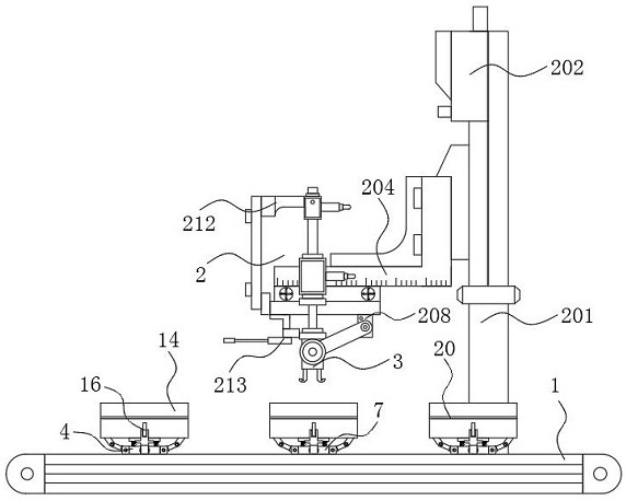
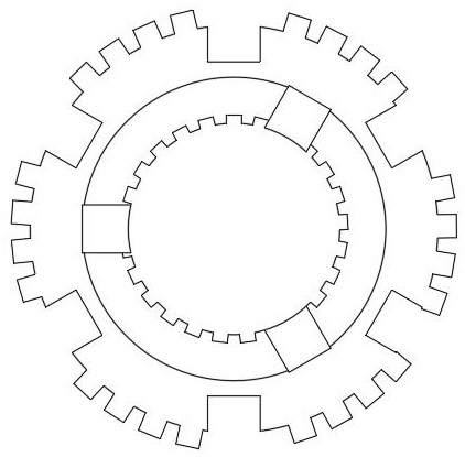
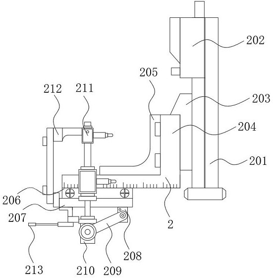
The invention discloses an automatic splined hub machining equipment with the function of integrally forming a tooth profile, and relates to the technical field of automobile part production. The equipment specifically comprises a conveying belt, a quantitative conveying mechanism, an inner hole end face axial linkage clamp, a movable clamping mechanism and a tooth profile forming composite die, wherein the quantitative conveying mechanism is arranged at the top end of the conveying belt, and the movable clamping mechanism is arranged on one side of the top end of the conveying belt. Accordingto the automatic splined hub machining equipment with the function of integrally forming the tooth profile, the tooth profile forming composite die is arranged, so that the problems that in the background art, the efficiency is low and the production cost is high due to common sequential single-tooth machining of existing splined hub material outer tooth spline machining equipment are perfectly solved; due to the design of the die, integral forming and final shaping of tooth bottoms, tooth tops and tooth sides of outer teeth of a splined hub are achieved, it is guaranteed that the dimensionalprecision of a workpiece meets the requirement after extrusion forming through uniform distribution of rolling components and release frames located in inner cavities of two layers of annular supports, and the applicability is higher.

Description

technical field [0001] The invention relates to the technical field of automobile parts production, in particular to an automatic spline hub processing equipment with the function of integrally forming tooth shapes. Background technique [0002] The automatic transmission is a key part of the car, and the spline hub in the transmission clutch is a key part of the transmission. Generally, the spline hub of the automatic transmission clutch of a car is shaped like a cylinder with a bottom surface, and there are teeth on the cylinder surface. The spline hub is the hub connected by the spline shaft. The spline shaft is a kind of mechanical transmission. It has the same function as the flat key, semi-circular key and oblique key. They all transmit mechanical torque. The rotating parts on the shaft also have corresponding keyways, which can keep rotating synchronously with the shaft. While rotating, some can also slide longitudinally on the shaft, such as gearbox shift gears, etc....

Claims


Application Information

Patent Timeline
IPC IPC(8): B21H5/02B21H9/00
CPCB21H5/02B21H9/00
Inventor 陈海华林佳妮钟海瑜
Owner 东莞市帕特慕可科技有限公司
Learn More