
Mechatronic pipe fitting cutting device

A cutting device and technology for pipe fittings, applied in the field of pipe fittings processing, can solve the problems of poor quality and a large number of burrs on the cutting surface of pipe fittings

Active Publication Date: 2021-01-15
ZHUZHOU HUAXIN PRECISION IND
View PDF6 Cites 1 Cited by
  • Summary
  • Abstract
  • Description
  • Claims
  • Application Information

AI Technical Summary

Problems solved by technology

When the traditional pipe fitting processing equipment is processing, the pipe fittings are fixed on the processing platform, and the cutting knife has a large number of burrs on the cutting surface of the pipe fittings after the cutting work is performed by the up and down displacement, and the quality is poor

Method used


Image

  • Mechatronic pipe fitting cutting device
  • Mechatronic pipe fitting cutting device
  • Mechatronic pipe fitting cutting device

Examples


Embodiment 1

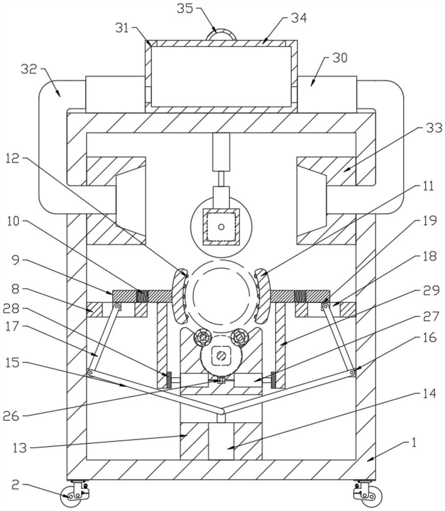
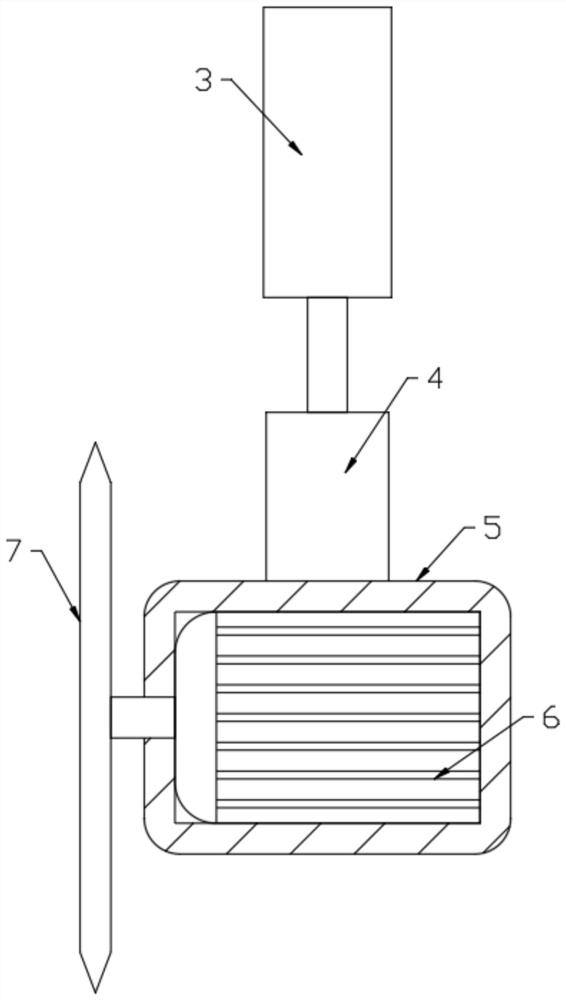
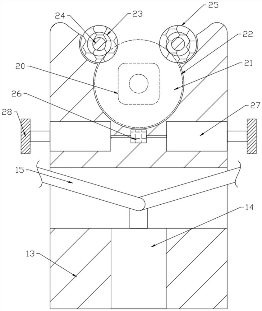
[0025]SeeFigure 1-5, An electromechanical integrated pipe cutting device, comprising a frame body 1, characterized in that the upper end of the frame body 1 is provided with a cutting assembly for cutting pipe fittings, and the inner sides of the frame body 1 are respectively fixedly connected with a fixing seat 8 and the fixing seat 8 There is a fixing assembly for fixing the pipe fittings. The frame body 1 is equipped with a column 13 at the lower end. The frame body 1 is provided with a driving assembly for driving the fixing assembly to work. The column 13 is provided with a rotating assembly for driving the pipe to rotate. There are failed components that drive fixed components temporarily failed.

[0026]Further, the lower end of the frame body 1 is provided with four rollers 2 with brake blocks to facilitate the device to move to different positions for work;

[0027]The cutting assembly includes a first hydraulic component 3, a connecting column 4, a case 5, a first motor 6, and a...

Embodiment 2

[0040]Further improvements are made on the basis of Embodiment 1, and the improvements are as follows: Fans 30 are provided on both sides of the upper end of the frame 1, and one end of the fan 30 is connected to the slag suction block 33 fixedly connected in the frame 1 through a connecting pipe 32. The other end of the fan 30 communicates with the slag storage cylinder 31 fixedly connected to the upper end of the frame body 1. The upper end of the slag storage cylinder 31 is threadedly connected with a cylinder cover 34, and the upper end of the cylinder cover 34 is fixedly connected with a grip ring 35. The fan 30 works through the connecting pipe 32 and the suction The slag block 33 absorbs the waste generated during the cutting work, and then is stored in the slag storage cylinder 31, and the grip ring 35 is rotated so that the cylinder cover 34 is removed from the slag storage cylinder 31 to clean the inside.


PUM


Abstract

The invention discloses a mechatronic pipe fitting cutting device. The cutting device comprises a frame body, wherein a cutting assembly used for cutting a pipe fitting is arranged at the upper end inthe frame body, fixing bases are fixedly connected to the two sides in the frame body respectively, fixing assemblies used for fixing the pipe fitting are arranged on the fixing bases, a stand columnis arranged at the lower end of the frame body, a driving assembly used for driving the fixing assemblies to work is arranged in the frame body, a rotating assembly for driving the pipe fitting to rotate is arranged in the stand column, and a failure assembly for driving the fixing assemblies to temporarily fail is arranged in the frame body. According to the cutting device, a second motor drivesa driving gear to rotate, then driven gears meshed with the driving gear drive rotating shafts to rotate, the rotating shafts rotate to enable rotating rollers to drive the pipe fitting to rotate after primary cutting, an inductor drives electric push rods to drive contact blocks to apply pressure to vertical columns during operation of the second motor, and then the clamping work of clamping blocks fails through moving columns under the action of springs, rotation of the pipe fitting is guaranteed, and then the cut face of the pipe fitting is neat without burrs after cutting.

Description

Technical field[0001]The invention relates to the technical field of pipe fitting processing, in particular to a mechanical and electrical integration pipe fitting cutting device.Background technique[0002]Mechatronics, also known as mechatronics engineering, is a type of mechanical engineering and automation. With the rapid development and wide application of computer technology, mechatronics technology has achieved unprecedented development. Mechatronics is an independent cross-discipline composed of computer technology, information technology, mechanical technology, electronic technology, control technology, and optical technology. Modern automatic production equipment can almost be said to be mechatronics equipment. When the traditional pipe processing equipment is processing, the pipe is fixed on the processing platform, and the cutting knife has a large number of burrs on the cutting surface of the pipe after the up and down displacement cutting work, and the quality is poor.Su...

Claims


Application Information

Patent Timeline
Patent Type & Authority Applications(China)
IPC IPC(8): B23D21/00B23D33/02
CPCB23D21/00B23D33/02
Inventor 曾远远张平
Owner ZHUZHOU HUAXIN PRECISION IND
Learn More