Hot-rolled U-rib double-sided welding method

A technology of double-sided welding and welding area, applied in welding equipment, welding accessories, arc welding equipment, etc., can solve the problems of low welding efficiency, insufficient weld penetration, large welding deformation, etc., to achieve high welding efficiency, The effect of improving construction efficiency and reducing welding material consumption

A technology of double-sided welding and welding area, applied in welding equipment, welding accessories, arc welding equipment, etc., can solve the problems of low welding efficiency, insufficient weld penetration, large welding deformation, etc., to achieve high welding efficiency, The effect of improving construction efficiency and reducing welding material consumption

CN112222580APending Publication Date: 2021-01-15WUCHUAN HEAVY ENG

Image

  • Hot-rolled U-rib double-sided welding method
  • Hot-rolled U-rib double-sided welding method

Examples


Embodiment 1

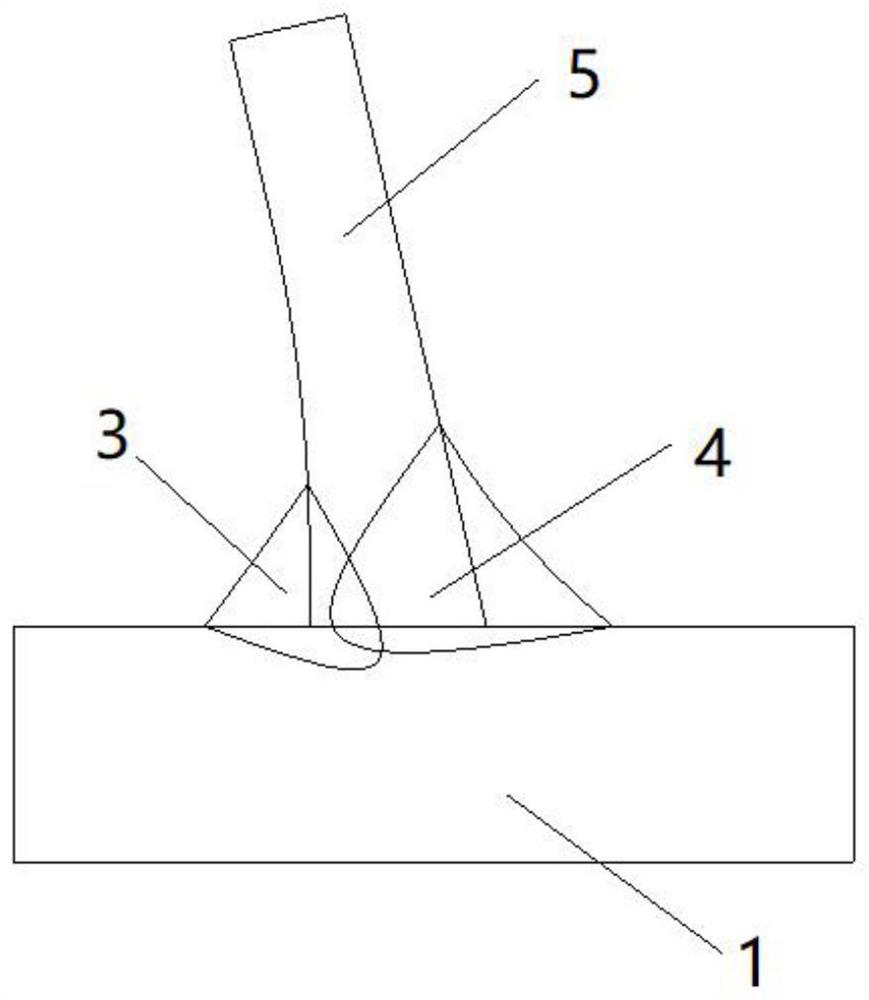
[0039] Such as figure 1 As shown, this embodiment provides a method for double-sided welding of hot-rolled U-ribs. The welding end thickness is 12 mm and the variable-section hot-rolled U-ribs 5 are as follows:

[0040] (1) Grind the area to be welded of the U rib, and polish and clean the rust, oil, paint, oxide layer, etc. of the area to be welded of the U rib until the area to be welded of the U rib is flat to facilitate welding.

[0041] (2) Grinding the area to be welded on the bridge deck 1 and the range of 20-30mm on both sides, grinding and cleaning the rust, oil, paint, oxide layer, etc. on the area to be welded on the bridge deck 1 until the area to be welded on the bridge deck 1 Flatten for subsequent steps.

[0042] (3) Put the U rib upside down on the bridge deck 1, so that the area to be welded of the U rib is attached to the surface of the area to be welded of the bridge deck 1, and the area to be welded of the U rib does not need to be grooved.

[0043] (4) W...

Embodiment 2

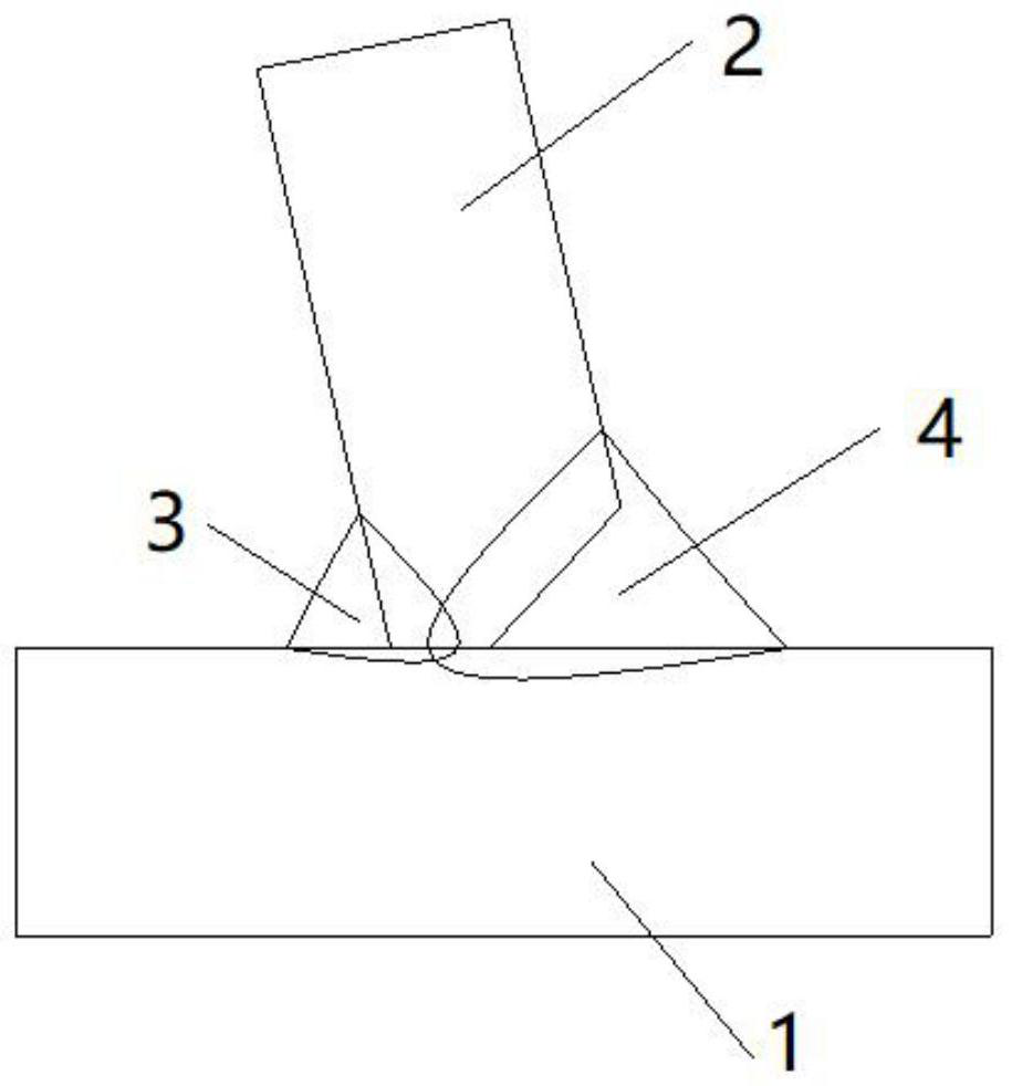
[0052] Such as figure 2 As shown, this embodiment provides a method for double-sided welding of hot-rolled U-ribs. The thickness of the welding end is 16 mm and the variable-section hot-rolled U-ribs 2 are as follows:

[0053] (1) Polish the area to be welded of the U rib, and polish and clean the rust, oil, paint, oxide layer, etc. on the area to be welded of the U rib until the area to be welded of the U rib is flat. This step is consistent with step (1) of Example 1.

[0054] (2) Grinding the area to be welded on the bridge deck 1 and the range of 20-30mm on both sides, grinding and cleaning the rust, oil, paint, oxide layer, etc. on the area to be welded on the bridge deck 1 until the area to be welded on the bridge deck 1 Flat. This step is consistent with step (2) of Example 1.

[0055] (3) Make a welding groove on the outside of the U rib to be welded. The welding area is in contact with the surface of the area to be welded on the bridge deck 1 .

[0056] (4) Weld...

Embodiment 3

[0065] This embodiment provides a double-sided welding method for hot-rolled U-ribs. This embodiment is consistent with Embodiment 2, except that step (6) is changed.

[0066] (6) The front wire adopts DC power supply, the control welding current is 910A, the welding voltage is 38.2V, the welding speed is 680mm / min, the rear wire welding current is 690A, the welding voltage is 34.7V, and the welding speed is 680mm / min.


PUM

PropertyMeasurementUnit
diameteraaaaaaaaaa
diameteraaaaaaaaaa
diameteraaaaaaaaaa

Abstract

The invention discloses a hot-rolled U-rib double-sided welding method which comprises the steps of grinding a to-be-welded area of a U-rib to enable the to-be-welded area of the U-rib to be a plane,grinding a to-be-welded area of a bridge deck slab to enable the to-be-welded area of the bridge deck slab after grinding to be a plane, placing the U-rib upside down on the bridge deck slab so as toenable the to-be-welded area of the U-rib to be attached to the surface of the to-be-welded area of the bridge deck slab, welding position-fixing weld seams on the outer side of the U-rib, welding theinner side of the U-rib, adopting a fine wire submerged arc welding process to perform welding at a horizontal position to form an inner side weld seam, welding the outer side of the U-rib, adoptinga double-wire and double-arc submerged arc welding process to perform welding at a ship-shaped position to form an outer side weld seam, and performing flaw detection on all the weld seams after welding is completed. According to the hot-rolled U-rib double-sided welding method, stable welding of the U-rib can be achieved under the condition that the U-rib is not provided with a welding groove oris provided with a relatively small welding groove, and the weld seams are smooth.

Description

technical field [0001] The invention relates to the technical field of steel structure bridge manufacturing, in particular to a double-sided welding method for hot-rolled U-ribs. Background technique [0002] Orthotropic steel decks are widely used in large-diameter bridges due to their light structure and short construction period. However, judging from the performance of the operating status of the built bridges, the bridges built in the early stage have successively suffered from structural fatigue cracking, and the fatigue resistance performance is worrying. [0003] Wuchuan Heavy Engineering Co., Ltd. proposed and applied the U-rib double-sided welding technology for orthotropic steel bridge decks, using special welding equipment to weld the fillet welds on the inside of the U ribs, and the U-rib inner welding technology to connect the U ribs and the bridge deck The connecting welds between the bridges are changed from single-sided fillet welds to double-sided fillet w...

Claims


Application Information

Patent Timeline
15 Jan 2021
Publication
CN112222580A
IPC
B23K9/18; B23K9/16; B23K9/235; B23K9/32
CPC
B23K9/18; B23K9/16; B23K9/235; B23K9/32
Inventors
张华; 王简