Stud-free tough combined bridge deck slab system

A combined bridge and toughness technology, applied in bridges, bridge parts, bridge materials, etc., can solve problems such as increased construction workload, sensitivity to local defects, erosion, etc., to block steel from the external environment, simple and efficient processing process, and improve toughness and durability effects

Active Publication Date: 2021-01-15
ZHEJIANG UNIV
View PDF6 Cites 2 Cited by
  • Summary
  • Abstract
  • Description
  • Claims
  • Application Information

AI Technical Summary

Problems solved by technology

However, there are still some problems in the existing steel-concrete composite bridge deck: First, in order to ensure the sufficient shear connection between steel and concrete and prevent the detachment of the two interfaces, more bolts are usually arranged between the two Nails (playing the dual role of shear resistance and pull resistance), which greatly increases the construction workload, and the fatigue performance of the structure is affected due to the existence of welds; second, the steel deck part of the composite bridge deck usually needs to be welded out of the plane Multiple stiffeners, which also increase the amount of construction and affect the fatigue performance of the structure; third, ordinary concrete materials are prone to cracking under tension, and are sensitive to local defects, and are prone to cracks under long-term loads, causing water and ion erosion, affecting The corrosion resistance and durability of the bridge deck will significantly increase the repair and maintenance costs of the bridge structure, causing a huge waste of manpower and material resources

Method used


Image

  • Stud-free tough combined bridge deck slab system
  • Stud-free tough combined bridge deck slab system
  • Stud-free tough combined bridge deck slab system

Examples


Embodiment Construction

[0032] Embodiments of the present invention will be described in detail below in conjunction with the accompanying drawings.

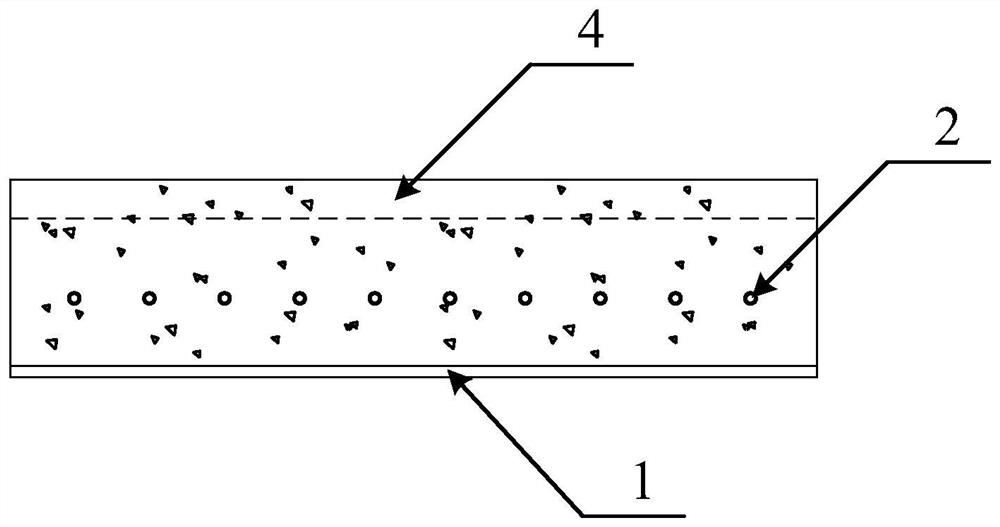
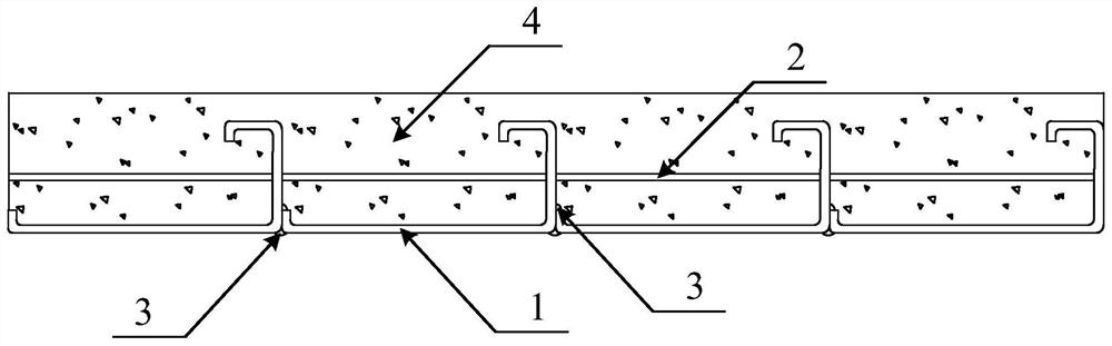
[0033] like figure 1 and figure 2 As shown, a studless ductile composite bridge deck system includes the following components: L-shaped beaded steel 1, longitudinal steel bars 2, and ultra-high toughness concrete 4.

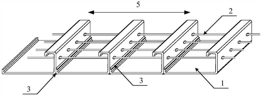
[0034] like image 3 As shown, the L-shaped curling steel 1 is continuously placed side by side along the longitudinal direction of the bridge deck, and the adjacent steel beams 1 are welded by two fillet welds 3 to form the steel skeleton of the bridge deck, of which 5 is the longitudinal direction of the bridge deck.

[0035] like Figure 4 As shown, a row of round holes is opened on the flange plate of the L-shaped curled steel 1, and the longitudinal reinforcement 2 passes through each flange plate of the L-shaped curled steel 1 through the round holes.

[0036] like figure 1 and figure 2 As shown, the ultra-high toughness con...


PUM

PropertyMeasurementUnit
lengthaaaaaaaaaa
diameteraaaaaaaaaa
elastic modulusaaaaaaaaaa

Abstract

The invention discloses a stud-free tough combined bridge deck slab system. The stud-free tough combined bridge deck slab system comprises L-shaped hemming profile steel, longitudinal reinforcing steel bars and ultrahigh-toughness concrete. The L-shaped hemming section steel is continuously arranged side by side in the longitudinal direction of a bridge deck, and adjacent section steel is welded through two fillet welds to form a bridge deck steel framework. A row of circular holes are formed in each L-shaped hemming section steel flange plate, and the longitudinal reinforcing steel bars penetrate through the L-shaped hemming section steel flange plates through the circular holes. And the ultrahigh-toughness concrete is poured on the bridge deck steel skeleton to play a role in protectingthe bridge deck steel skeleton. In the combined bridge deck slab system provided by the invention, the ultra-high toughness concrete can ensure that tiny cracks of below 100 microns are not generatedor only generated under the action of various loads, and the toughness and durability of the structure are improved; the structural mode of combining the L-shaped hemming profile steel and the longitudinal reinforcing steel bars achieves the effective anti-shearing and anti-pulling effects, the effects of studs and transverse reinforcing steel bars are replaced, so that the material cost and the construction complexity are greatly reduced, and the fatigue performance is excellent.

Description

technical field [0001] The invention relates to the technical field of structural engineering, in particular to a studless tough composite bridge deck system. Background technique [0002] With the continuous advancement of my country's infrastructure construction process, people realize that the convenience of intra-city traffic and inter-city traffic greatly affects the development of the national economy and social progress; therefore, the country has achieved great development in road and bridge engineering in recent decades . Among them, bridge structures are not only widely used in urban overpasses, subway light rails, high-speed railways, etc., but also in river-crossing and sea-crossing structures. In recent years, with the construction of super-large bridge projects such as the Hong Kong-Zhuhai-Macao Bridge and the Hangzhou Bay Bridge, bridge structures at home and abroad are facing unprecedented opportunities for development. In the construction of bridge structur...

Claims


Application Information

Patent Timeline
Patent Type & Authority Applications(China)
IPC IPC(8): E01D19/12C04B28/00E01D101/26
CPCE01D19/125C04B28/00E01D2101/266C04B18/08C04B18/146C04B18/141C04B18/103
Inventor 李庆华徐世烺童精中
Owner ZHEJIANG UNIV
Why Eureka
Try Eureka