Automatic testing device for scale
An automatic testing device and scale body technology, which is applied in the direction of weighing equipment testing/calibration, etc., can solve the problems of manual operation such as high labor intensity, different strength and position, and large measurement error, so as to reduce labor intensity, improve accuracy, The effect of improving work efficiency
- Summary
- Abstract
- Description
- Claims
- Application Information
AI Technical Summary
Problems solved by technology
Method used
Image
Examples
Embodiment 1
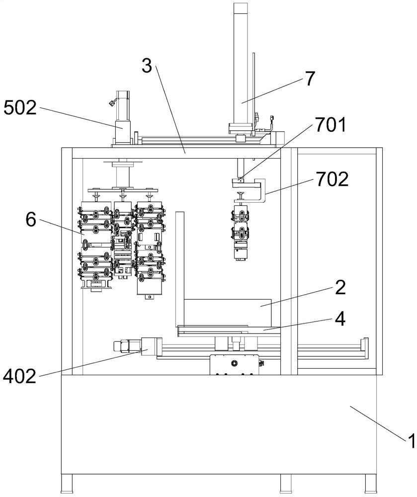
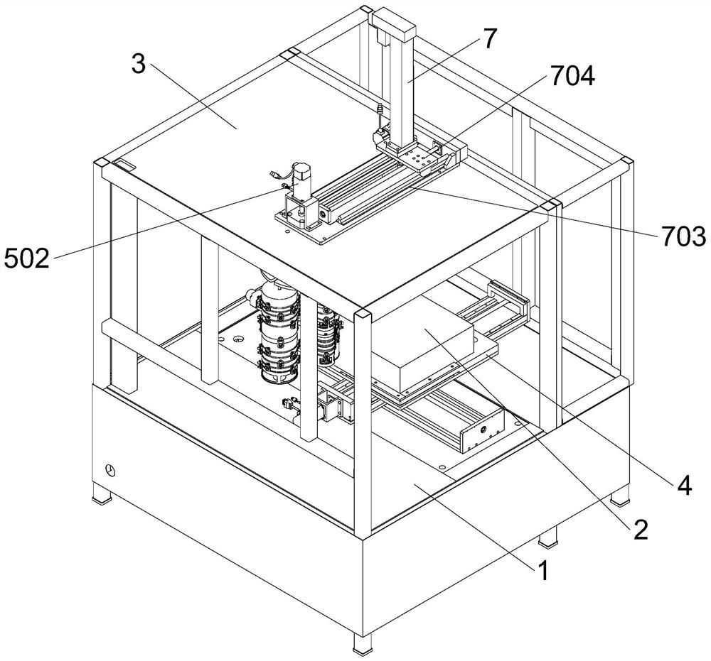
[0038] The automatic test device for scales of the present invention comprises a workbench 1, a scale body 2 is arranged on the upper end of the workbench 1, a top plate 3 is arranged above the workbench 1, and a rotatable weight store is arranged above the workbench 1 5. A plurality of weight strings 6 are suspended from the weight storehouse 5. A telescopic assembly 7 capable of lifting and moving is arranged above the workbench 1. A mechanical claw 702 capable of grabbing the weight string 6 is installed at the lower end of the telescopic assembly 7. The assembly 7 is equipped with a sliding seat 704 which can move in a direction close to the weight storehouse 5 .
[0039]After adopting the above-mentioned technical scheme: the present invention is provided with a rotatable weight storehouse 5, a plurality of weight strings 6 are suspended from the weight storehouse 5, and a mechanical claw 702 capable of grabbing the weight strings 6 is set on the upper end of the workbench...
Embodiment 2
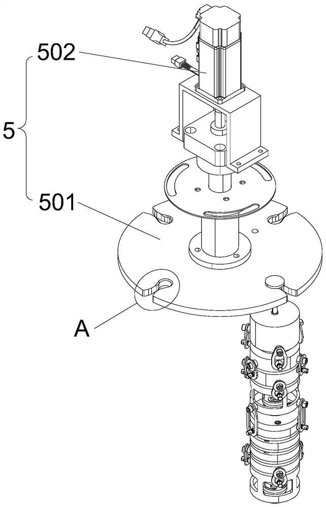
[0041] This embodiment is further optimized on the basis of Embodiment 1 as follows: the weight storehouse 5 includes a servo motor 502 and a rotating disk 501; The rotating disks 501 are connected to each other, the periphery of the rotating disk 501 is provided with a plurality of first placement holes 5011, the outer wall of the first placement holes 5011 is provided with a first guide groove 5013 penetrating through the side wall of the rotating disk 501, and the upper end of the weight string 6 is arranged There is a positioning column 8 with a diameter smaller than the first guide groove 5013 , and a first limiting block 801 is provided on the upper end of the positioning column 8 .
[0042] After adopting the above technical solution: the rotation of the rotating disk 501 is driven by the servo motor 502, which facilitates the control of each rotation angle of the rotating disk 501, and ensures that after each rotation of a certain angle, the positioning columns 8 of the...
Embodiment 3
[0044] This embodiment is further optimized on the basis of Embodiment 1 as follows: the positioning column 8 is provided with a second limit block 802 located at the lower end of the first limit block 801, the first limit block 801 and the second limit block The distance between the blocks 802 is greater than the thickness of the rotating disk 501, the second placement hole 7021 is opened through the mechanical claw 702, the side wall of the second placement hole 7021 is provided with a second guide groove 7023 penetrating the side wall of the mechanical claw 702, the second The width of the guide groove 7023 is greater than the diameter of the positioning post 8 .
[0045] After adopting the above technical solution: the mechanical claw 702 is provided with a second placement hole 7021 and a second guide groove 7023, when the weight string 6 needs to be grasped, the positioning column 8 located below the second limit block 802 passes through the second guide groove 7023 Ente...
PUM
 Abstract
Description
Claims
Application Information
 - R&D
- Intellectual Property
- Life Sciences
- Materials
- Tech Scout
- Unparalleled Data Quality
- Higher Quality Content
- 60% Fewer Hallucinations
Browse by: Latest US Patents, China's latest patents, Technical Efficacy Thesaurus, Application Domain, Technology Topic, Popular Technical Reports.
© 2025 PatSnap. All rights reserved.Legal|Privacy policy|Modern Slavery Act Transparency Statement|Sitemap|About US| Contact US: help@patsnap.com


