Supercharge Your Innovation With Domain-Expert AI Agents!

Laser projection system and light source device

A technology of laser projection and light source device, applied in projection devices, optics, instruments, etc., can solve problems such as unfavorable fluorescence conversion

Active Publication Date: 2021-01-15
QINGDAO HISENSE LASER DISPLAY CO LTD
View PDF11 Cites 1 Cited by
  • Summary
  • Abstract
  • Description
  • Claims
  • Application Information

AI Technical Summary

Problems solved by technology

However, since the outgoing light of the laser is coherent light, the spot projected on the fluorescent wheel is a Gaussian spot with high energy, which is not conducive to fluorescence conversion

Method used


Image

  • Laser projection system and light source device
  • Laser projection system and light source device
  • Laser projection system and light source device

Examples


Embodiment Construction

[0036] In order to make the purpose, technical solutions and advantages of the present invention clearer, the present invention will be further described in detail below in conjunction with the accompanying drawings. Obviously, the described embodiments are only some of the embodiments of the present invention, rather than all of them. Based on the embodiments of the present invention, all other embodiments obtained by persons of ordinary skill in the art without making creative efforts belong to the protection scope of the present invention.

[0037] The laser projection system and light source device provided by specific embodiments of the present invention will be described in detail below with reference to the accompanying drawings.

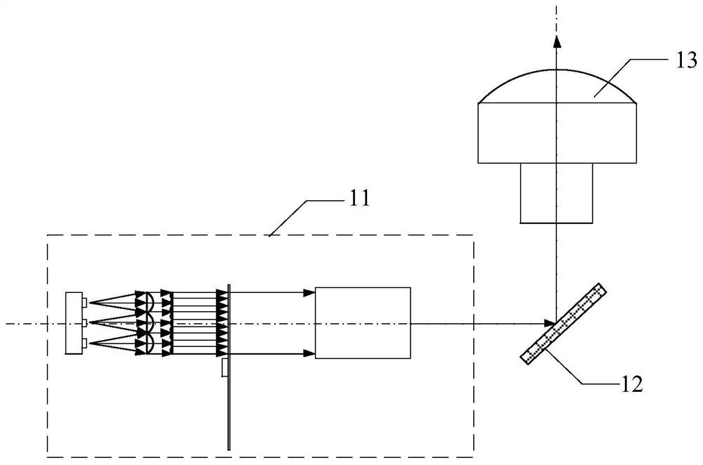
[0038] like figure 1 As shown, the embodiment of the present invention provides a laser projection system, including: a light source device 11, a light valve modulation assembly 12 located at the light output side of the light source device, ...


PUM

PropertyMeasurementUnit
Focal lengthaaaaaaaaaa

Abstract

The invention discloses a laser projection system and a light source device. The light source device comprises a laser array, a first fly-eye lens array located on the light-emitting side of the laserarray, a second fly-eye lens array located on the light-emitting side of the first fly-eye lens array and a fluorescent wheel located on the light-emitting side of the second fly-eye lens array, wherein each laser device in the laser array is in one-to-one correspondence with each lens in the first fly-eye lens array, one lens in the first fly-eye lens array corresponds to at least two lenses inthe second fly-eye lens array, the first fly-eye lens array is used for collimating emergent light of the laser array, and the second fly-eye lens array is used for homogenizing the emergent light ofthe first fly-eye lens array. By arranging the first fly-eye lens array and the second fly-eye lens array on the light emitting side of the laser array, light beams emitted by the laser array can be fully homogenized, so that the energy density of light rays emitted by a laser when the light rays reach a fluorescent wheel is properly reduced, and the excitation efficiency of fluorescence is improved.

Description

technical field [0001] The invention relates to the field of display technology, in particular to a laser projection system and a light source device. Background technique [0002] In recent years, the 0.47” DMD miniature projection system has been widely used in various fields due to its low price and small size. However, with the continuous improvement of market demand, projectors with high brightness, large size and high resolution Most of them have attracted market attention. Due to the etendue of light-emitting diodes (LEDs), the luminous power per unit area is low, and it is difficult to improve the brightness of small-sized projection systems such as 0.47”DMD, which cannot meet market demand. [0003] In response to this problem, a projection system using lasers as a projection light source has been proposed. Lasers have the advantages of high brightness, high collimation, etc., and can provide higher brightness light sources for laser projection systems. However, si...

Claims


Application Information

Patent Timeline
IPC IPC(8): G03B21/20
CPCG03B21/208G03B21/2013G03B21/204G03B21/206G03B21/2033
Inventor 李巍
Owner QINGDAO HISENSE LASER DISPLAY CO LTD
Features
  • R&D
  • Intellectual Property
  • Life Sciences
  • Materials
  • Tech Scout
  • Unparalleled Data Quality
  • Higher Quality Content
  • 60% Fewer Hallucinations
Learn More