Winding device of amorphous three-dimensional wound core transformer wire foil integrated winding machine and operation method of winding device

A three-dimensional wound iron core and transformer technology, which is used in inductor/transformer/magnet manufacturing, coil manufacturing, electrical components, etc., can solve problems such as easy discovery, high manufacturing and maintenance costs, complex structure, etc. The number of turns can be adjusted to avoid the effect of coil vibration

Pending Publication Date: 2021-01-15
CECEP XIAN QIYUAN MECHANICAL & EIECTRICAL EQUIP CO LTD
View PDF2 Cites 6 Cited by
  • Summary
  • Abstract
  • Description
  • Claims
  • Application Information

AI Technical Summary

Problems solved by technology

[0003] The Chinese Invention Patent No. 201910398106.4 published on August 2, 2019 describes an automatic winding mechanism for an amorphous triangular three-dimensional wound iron core foil wire, which can avoid core vibration, reduce the number of clamping times of the iron core, and realize low-voltage foil and high-voltage wire The advantages of one-step winding automatic operation can especially reduce the mechanical vibration or extrusion of the iron core and avoid damage to the iron core. However, combined with the structural schematic diagram of the invention patent No. 201920684653.4 applied for on the same day, it is not difficult to find that, Its structure is relatively complex, and its manufacturing and maintenance costs are relatively high

Method used


Image

  • Winding device of amorphous three-dimensional wound core transformer wire foil integrated winding machine and operation method of winding device
  • Winding device of amorphous three-dimensional wound core transformer wire foil integrated winding machine and operation method of winding device
  • Winding device of amorphous three-dimensional wound core transformer wire foil integrated winding machine and operation method of winding device

Examples


Embodiment 1

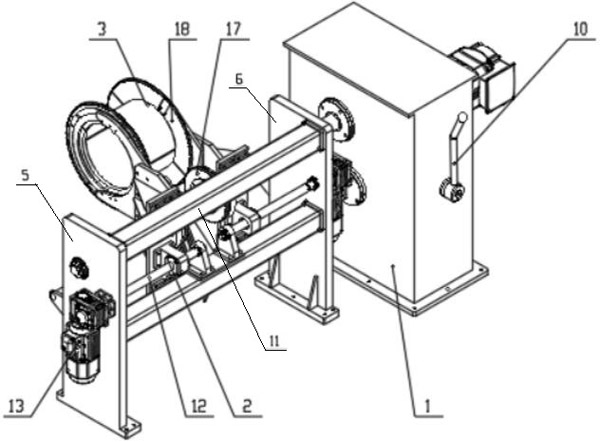
[0061] figure 1The winding device of an amorphous three-dimensional wound core transformer wire and foil integrated winding machine shown includes a main shaft transmission box 1, a winding gear set moving device 2, a winding gear set 3, a coil pressing device 4, and a left wall plate 6 and the right wallboard 5; it is not difficult to see from this figure that the left wallboard 6, the right wallboard 5 and the main shaft transmission box 1 are arranged side by side to set the basic layout for the assembly of the whole device, and the natural winding gear set moving device 2 and the The winding gear set 3 that suspends the coil is placed between the left wallboard 6 and the right wallboard 5; and the coil pressing device 4 is placed between the left wallboard 6 and the right wallboard 5, and is located in the The bottom is used to compress the coil when winding the foil low-voltage coil to prevent the coil from loosening during the winding process. During actual operation, t...

Embodiment 2

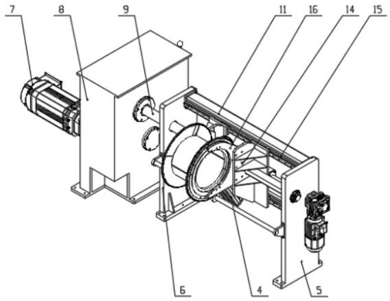
[0064] combined with figure 2 It can be seen that the winding gear set 3 is two groups, arranged symmetrically in the axial direction of the main shaft 9, including a carriage 14, a linear guide rail 15, a support frame 16, a driving gear 17 and a driven gear module 18; two of the linear guide rails 15 are respectively installed on the beam 11 between the left wallboard 6 and the right wallboard 5; the carriage 14 is installed on the linear guide rail 15, and can slide along the length direction of the guide rail on the linear guide rail 15; the end of the support frame 16 is " C”-shaped structure; one end of the support frame 16 is installed on the carriage 14, and the other end is installed with a driven gear module 18, which is meshed with the driving gear 17; the driving gear 17 is set on the main shaft 9, and It can slide axially on the main shaft 9.

[0065] And the winding gear group moving device 2 is installed on the crossbeam 11; This winding gear group moving devi...

Embodiment 3

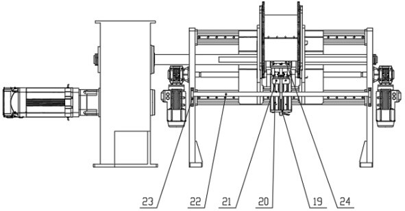
[0068] combined with image 3 It can be seen that the coil pressing device 4 is installed between the left wallboard 6 and the right wallboard 5, and is located at the lower part of the coil. The coil pressing device 4 consists of a lower support 19, a cylinder 20, an upper support 21, a guide rod 22, a The rod installation support 23 and the pressing wheel 24 are composed; one end of the lower support 19 is connected with the linear guide rail 15 on the beam 11, and the other end is connected with the rear end of the cylinder 20; one end of the upper support 21 is connected with the front end of the cylinder 20, and the other end is connected with the guide rod 22 are hinged; the cylinder 20 ends are equipped with pinch wheels 24; Stretch down.

[0069] Such as Figure 4 As shown, when working, the iron core is fixed to a fixed position, the driven gear module 18 is installed on the iron core column, and the pair of winding gear sets 3 are adjusted to a suitable width by ad...


PUM


Abstract

The invention relates to a winding device of an amorphous three-dimensional wound core transformer wire foil integrated winding machine and an operation method of the winding device. The winding device comprises a main shaft transmission box, a winding gear set moving device, a winding gear set, a coil pressing device, a left wall plate, a right wall plate and a control assembly. The left wall plate and the right wall plate are arranged side by side with the main shaft transmission case, the winding gear set moving device is located between the left wall plate and the right wall plate, the winding gear set is driven by the winding gear set moving device to transversely move to adapt to coils of different heights, and the coil pressing device is designed between the left wall plate and theright wall plate and located below the coils. According to the device, the technology that the coil is completely suspended through the winding gear set is adopted, damage to an iron core in the winding process is avoided, the center distance between a driving gear and a driven gear is fixed, the coils vibrates in the winding process, the gear abrasion speed and noise generated in the coil windingprocess are reduced, and the winding speed and coil quality are improved; and integrated winding of a low-voltage foil type coil and a high-voltage wire type coil can be realized.

Description

technical field [0001] The invention belongs to the technical field of winding machines for amorphous three-dimensional wound core transformers, and in particular relates to a winding device and an operating method for an amorphous three-dimensional wound core transformer wire and foil integrated winding machine. Background technique [0002] The material of the amorphous strip is thin and brittle. Therefore, the amorphous three-dimensional wound core made of the amorphous strip is difficult to withstand a large external force. It has become a difficult problem on the core column of the crystal three-dimensional wound core. [0003] The Chinese Invention Patent No. 201910398106.4 published on August 2, 2019 describes an automatic winding mechanism for an amorphous triangular three-dimensional wound iron core foil wire, which can avoid core vibration, reduce the number of clamping times of the iron core, and realize low-voltage foil and high-voltage wire The advantages of on...

Claims


Application Information

Patent Timeline
Patent Type & Authority Applications(China)
IPC IPC(8): H01F41/061H01F41/06H01F41/098
CPCH01F41/06H01F41/061H01F41/098
Inventor 赵鹏涛赵丹白国栋闫超虎郭毅刘晶张华杰李彦虎
Owner CECEP XIAN QIYUAN MECHANICAL & EIECTRICAL EQUIP CO LTD
Why Eureka
Try Eureka