Driving device and control method thereof and electronic equipment

A driving device and driving circuit technology, applied in the electrical field, can solve the problems of increasing the on-resistance of the lower end tube, reducing the grid voltage of the lower end tube, affecting the performance of the class D power amplifier, etc., to achieve cost saving, good voltage stability and The effect of circuit performance

Active Publication Date: 2021-01-15
SHANGHAI AWINIC TECH CO LTD
View PDF5 Cites 0 Cited by
  • Summary
  • Abstract
  • Description
  • Claims
  • Application Information

AI Technical Summary

Problems solved by technology

However, the voltage of the battery will decrease as the usage time increases, resulting in a decrease in the grid voltage of the lower end tube and an increase in the on-resistance of the lower end tube, which will affect the efficiency of power amplification and generate greater heat.
Moreover, because the battery voltage changes, the edge slope of the output signal of the Class D power amplifier will also change, which will affect the performance of the Class D power amplifier.

Method used


Image

  • Driving device and control method thereof and electronic equipment
  • Driving device and control method thereof and electronic equipment
  • Driving device and control method thereof and electronic equipment

Examples


Embodiment Construction

[0036] The technical solutions in the embodiments of the present application will be clearly and completely described below in conjunction with the accompanying drawings. Apparently, the described embodiments are only some of the embodiments of the present application, not all of them. Based on the embodiments in this application, all other embodiments obtained by those skilled in the art without making creative efforts belong to the scope of protection of this application. In the case of no conflict, the following embodiments and technical features thereof can be combined with each other.

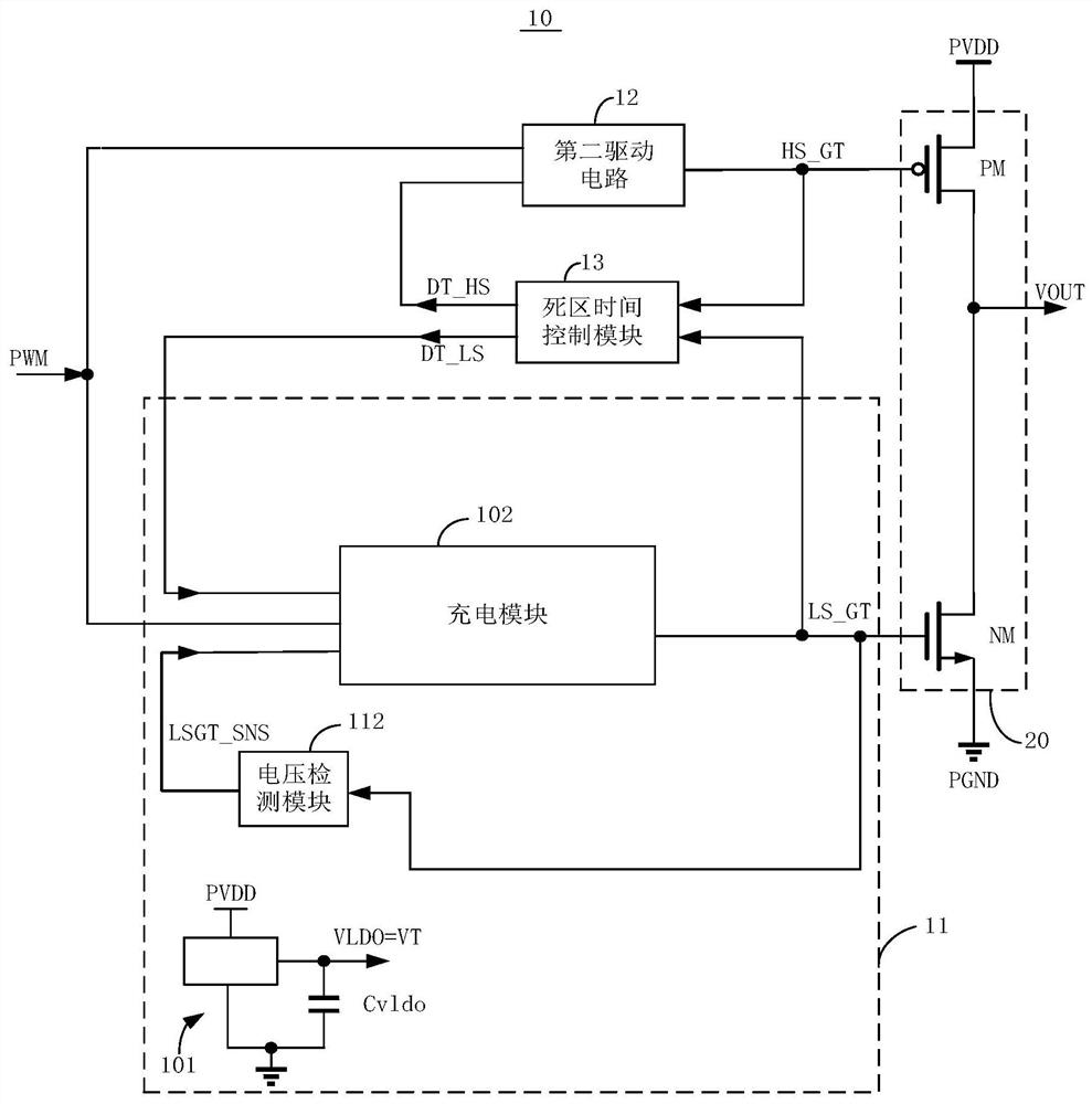
[0037] see figure 1 , is a partial circuit diagram of an embodiment of the driving device 10 of the present application. For example but not limited to, the driving device 10 can be applied to a class D audio power amplifier circuit. The driving device 10 can receive a pulse width modulation signal PWM from an external pulse width modulation circuit (not shown), and output a correspondin...


PUM


Abstract

The invention discloses a driving device, which is used for driving a power output circuit, and comprises a first driving circuit, wherein the power output circuit comprises a first power tube, the first driving circuit is used for providing a first gate voltage to the gate electrode of the first power tube so as to control the on or off of the first power tube, the first driving circuit comprisesa charging module, a voltage detection module and a voltage source, the voltage source provides a charging voltage, the gate electrode of the first power tube is charged to a first voltage by using apower supply voltage, and when the voltage detection module detects that the first gate voltage reaches the first voltage, the charging module is controlled to be switched to charge by using the charging voltage. The invention further discloses a control method of the driving device and electronic equipment. The device is relatively low in cost.

Description

technical field [0001] The present application relates to electricity, in particular to a driving device, a control method thereof, and an electronic device. Background technique [0002] Nowadays, more and more product applications require power chips such as class-D power amplifiers and motor drivers to have high-voltage driving capabilities and provide large output power. The working voltage of devices usually needs to be above 10V. High-voltage devices with high performance and small on-resistance usually use thin gate oxide technology devices, and the normal operating voltage of the gate usually requires a low voltage (about 5V) range. Currently. In the prior art, when the lower transistor (NMOS power transistor) is turned on, the method for charging the grid of the lower transistor includes using a battery to charge the grid of the lower transistor. However, the voltage of the battery will decrease as the usage time increases, resulting in a decrease in the grid volt...

Claims


Application Information

Patent Timeline
Patent Type & Authority Applications(China)
IPC IPC(8): H02M1/08H02M1/088
CPCH02M1/08H02M1/088
Inventor 杨志飞
Owner SHANGHAI AWINIC TECH CO LTD
Why Eureka
Try Eureka