Digital printing shearing machine
A digital printing and shearing machine technology, which is applied in metal processing and other fields, can solve the problems of reducing work efficiency and unable to cut printed paper
- Summary
- Abstract
- Description
- Claims
- Application Information
AI Technical Summary
Problems solved by technology
Method used
Image

Examples
specific Embodiment approach 1
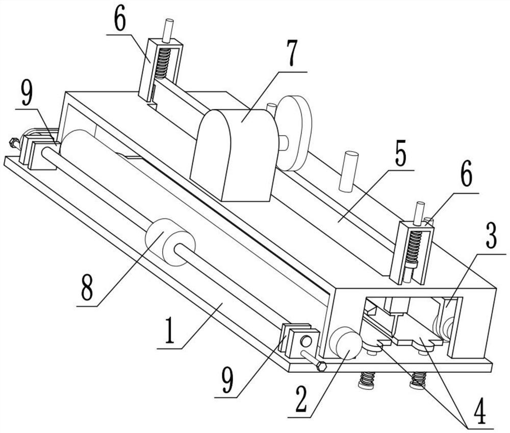
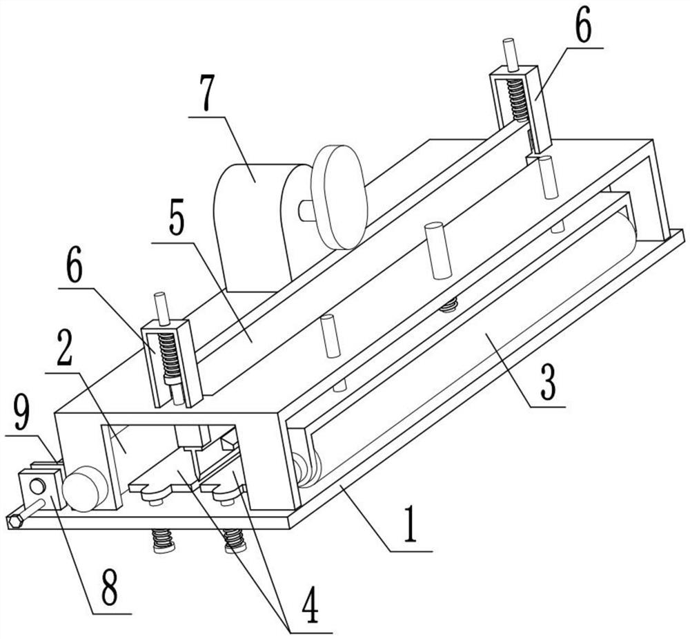
[0034] Combine below Figure 1-12Describe this embodiment, the present invention relates to the technical field of digital printing, more specifically a digital printing shearing machine, including a bottom support device 1, a paper conveying device 2, an extruding discharge member 3, an extruding fixing member 4, a lift Cutting member 5, connecting limit member 6, lifting power device 7, auxiliary transmission device 8 and width adjustment device 9, place the printing paper on the fixed bottom plate 1-1 and under the drive roller 2-2, start the motor I2- 3. The printing paper can be moved by the rotating drive roller 2-2. At this time, the printing paper will move to the bottom of the extrusion roller 3-2, and the rotation of the extrusion roller 3-2 will drive the printing paper to move. When the printing paper moves to a certain extent After the distance, the transmission roller 2-2 and the displacement roller 3-2 will stop rotating, and the motor III7-1 will be started at ...
specific Embodiment approach 2
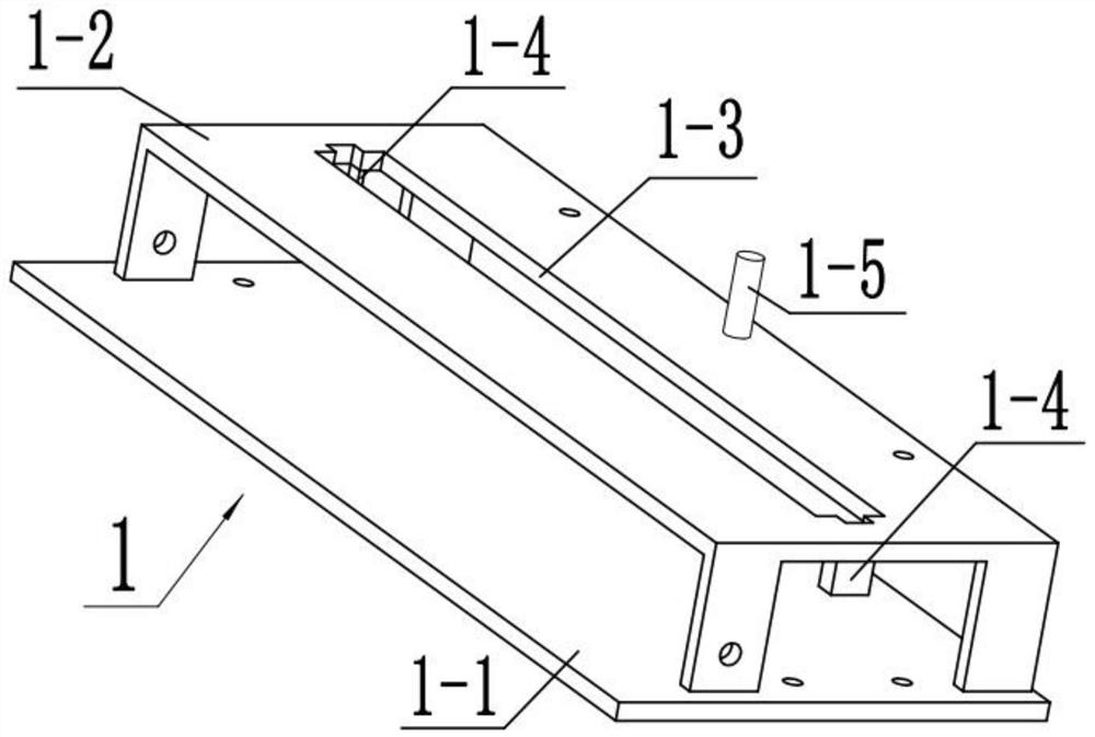
[0037] Combine below Figure 1-12 Describe this embodiment, this embodiment will further explain Embodiment 1. The bottom support device 1 includes a fixed bottom plate 1-1, a support frame 1-2, a connecting slot 1-3, a limit chute 1-4 and The electromagnet sliding cavity 1-5, the fixed base plate 1-1 play the role of bearing connection, the fixed base plate 1-1 can be connected in the digital printing, the fixed base plate 1-1 is fixedly connected with the support frame 1-2, the support frame The body 1-2 plays the role of bearing support, and the support frame body 1-2 is provided with a connecting slot 1-3. The position chute 1-4 can provide sliding space for the lifting horizontal plate 4-1, so that the lifting horizontal plate 4-1 can only slide up and down, and the top of the right end of the supporting frame body 1-2 is fixedly connected with an electromagnet sliding cavity 1-5 , the electromagnet sliding chamber 1-5 is fixedly connected with an electromagnet, when the...
specific Embodiment approach 3
[0039] Combine below Figure 1-12 Describe this embodiment, this embodiment will further explain Embodiment 2, the paper conveying device 2 includes a transmission shaft 2-1, a transmission roller 2-2, a motor I2-3 and a pulley I2-4, the transmission shaft 2- Both ends of 1 are rotatably connected with the support frame 1-2, and the transmission shaft 2-1 is fixedly connected with the transmission roller 2-2, the outer surface of the transmission roller 2-2 is provided with rubber, and the rear transmission roller 2 is provided with the rubber There will be greater friction between -2 and the printing paper, which is convenient to drive the printing paper to move. The motor I2-3 is fixedly connected to the support frame 1-2 and the output shaft is fixedly connected to the transmission shaft 2-1. The transmission shaft 2 The front end of -1 is fixedly connected with belt pulley I2-4, and belt pulley I2-4 can drive belt pulley II8-4 to rotate, and starter motor I2-3 can drive tr...
PUM
 Abstract
Description
Claims
Application Information
 - R&D
- Intellectual Property
- Life Sciences
- Materials
- Tech Scout
- Unparalleled Data Quality
- Higher Quality Content
- 60% Fewer Hallucinations
Browse by: Latest US Patents, China's latest patents, Technical Efficacy Thesaurus, Application Domain, Technology Topic, Popular Technical Reports.
© 2025 PatSnap. All rights reserved.Legal|Privacy policy|Modern Slavery Act Transparency Statement|Sitemap|About US| Contact US: help@patsnap.com