Assembly process of die assembly

An assembly process and component technology, applied in the field of magnetrons, can solve the problems of immature assembly process and inability to guarantee quality, and achieve the effects of improving heating efficiency and user safety, avoiding microwave leakage and high coordination.

Active Publication Date: 2021-01-19
GUANGDONG GALANZ MICROWAVE OVEN & ELECTRICAL APPLIANCES MFG +1
View PDF12 Cites 2 Cited by
  • Summary
  • Abstract
  • Description
  • Claims
  • Application Information

AI Technical Summary

Problems solved by technology

[0005] In view of this, the present invention aims to propose a die assembly assembly process to solve the problem that the die assembly assembly process in the prior art is immature and cannot guarantee quality

Method used


Image

  • Assembly process of die assembly
  • Assembly process of die assembly
  • Assembly process of die assembly

Examples


Embodiment 1

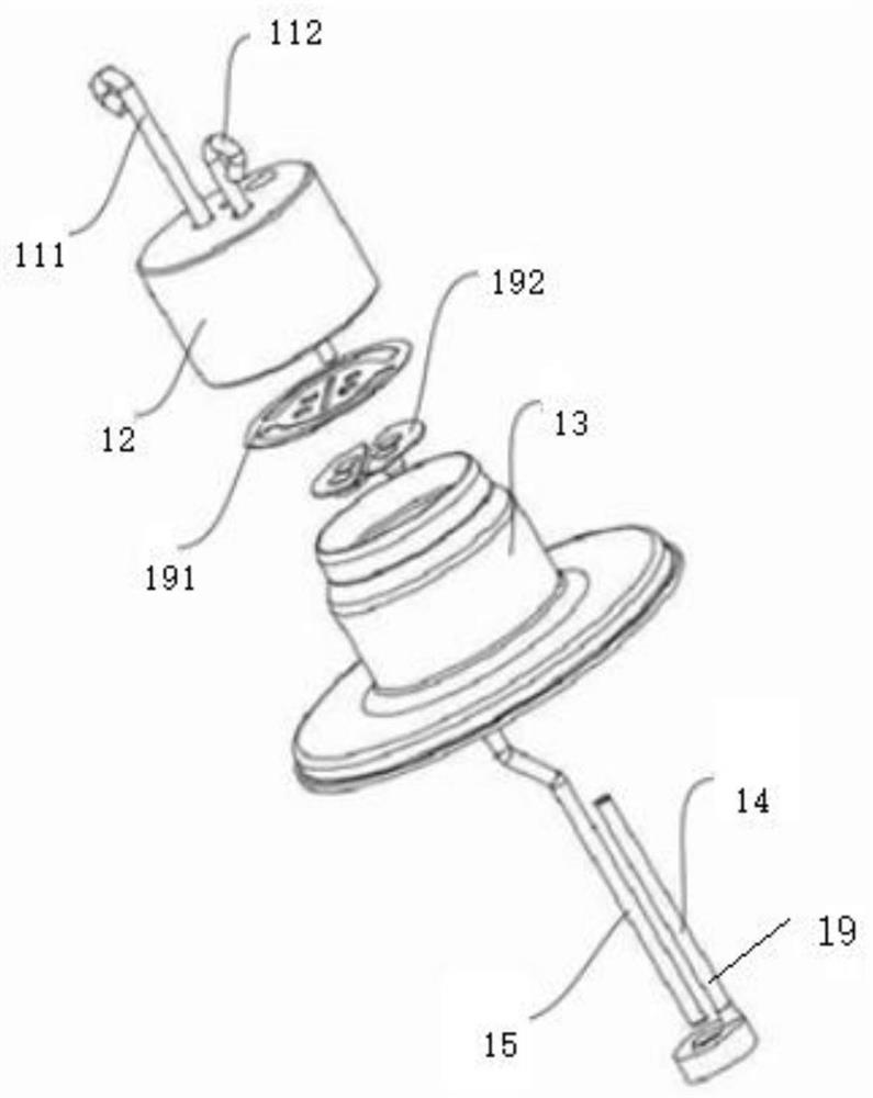
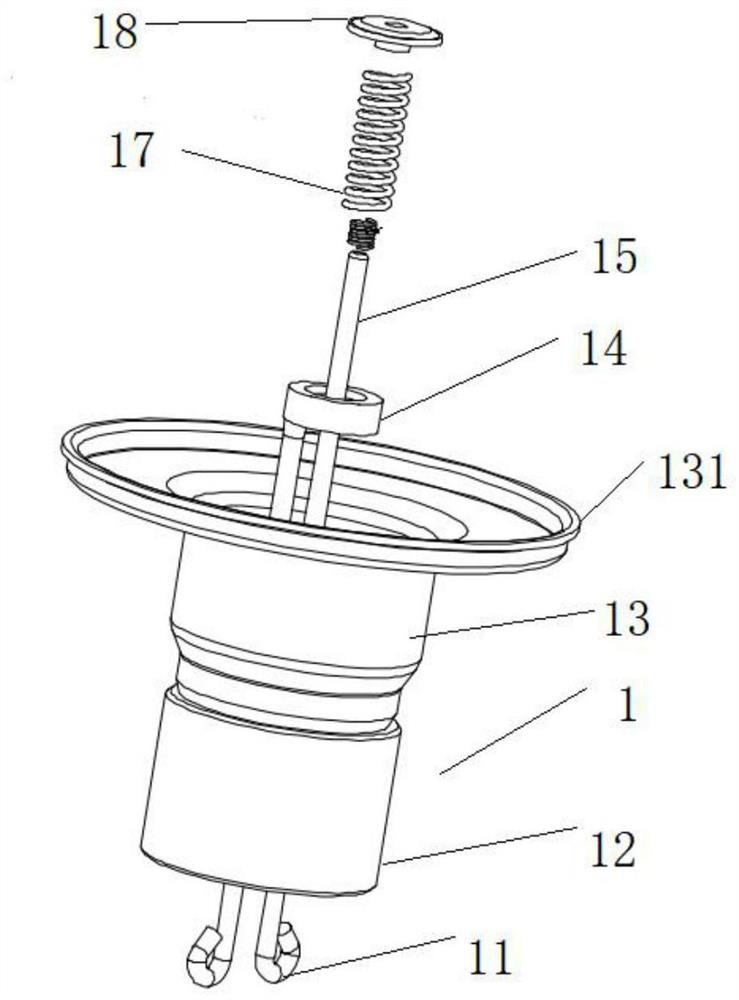
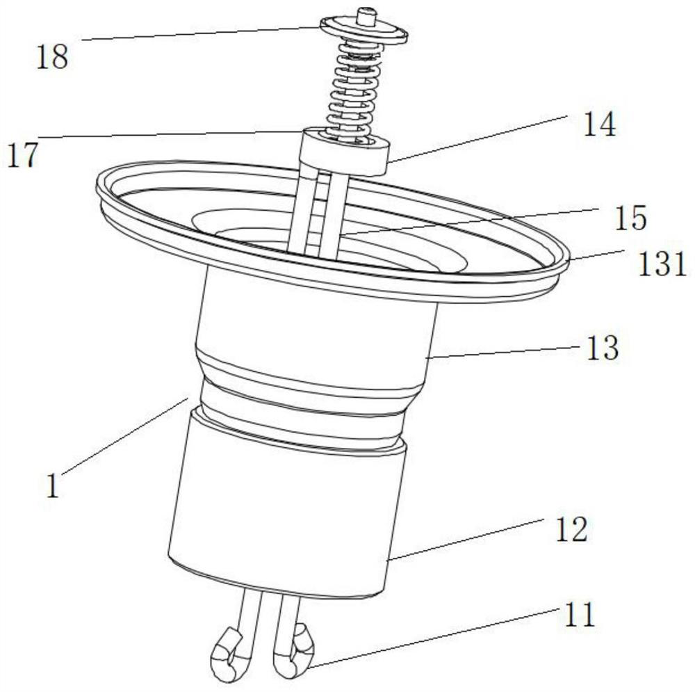
[0093] Embodiment 1 Assembly of cathode assembly 1

[0094] Such as Figure 1-3 The cathode assembly 1 shown includes a terminal 11 , a support body 12 , a cathode solder plate 191 , a reflection plate 192 , a K-side tube 13 , and a lead assembly 19 arranged in sequence. The terminal 11 includes a first terminal 111 and a second terminal 112 which pass through the support body 12 and the cathode solder plate 191 sequentially and are fixed on the upper surface of the reflector 192 . During assembly, the upper ends of the first terminal 111 and the second terminal 112 are connected to the power supply of the magnetron; the support body 12 is made of ceramic material, and the lead wire assembly 19 includes a lower end cap assembly 14 and a long lead wire 15. One end of the long lead wire 15 passes through the lower end cap assembly 14, and is used for installing the filament after adjusting the concentricity. The lower end cap assembly 14 and the other end of the long lead wire...

Embodiment 2

[0170] Embodiment 2 Assembly of anode assembly 2

[0171] In order to facilitate the introduction of the assembly relationship, the anode assembly 2 is introduced first, such as Figure 16-29 As shown, the anode assembly 2 includes an anode cylinder 23, and a plurality of anode plates 29 are arranged in the anode cylinder 23, and the plurality of anode plates 29 are equidistant and coaxially arranged in the anode cylinder 23 radially. Specifically, the anode plate 29 is provided with an antenna slot 291, and the antenna slots 291 on two adjacent anode plates 29 have different orientations, and a plurality of the anode plates 29 are fixedly connected to the inner peripheral surface of the anode cylinder 23 , On the plurality of anode plates 29 are provided pressure equalizing rings 22 , and the pressure equalizing rings 22 include a large pressure equalizing ring 221 and a small pressure equalizing ring 222 . The large pressure equalizing ring 221 and the small pressure equali...

Embodiment 3

[0237] Embodiment 3 Assembly of exhaust pipe assembly

[0238] In order to solve the unreasonable structural design of the brazing mold in the prior art, especially the problem of poor concentricity defined by the mold, this embodiment proposes an assembly mold for the magnetron exhaust pipe assembly 3, as shown in the attached Figure 32-37 As shown, the assembly mold includes an upper mold 71 and a lower mold 72. A hollow main cavity 710 is provided inside the upper mold 71. The upper mold 71 is sleeved outside the exhaust pipe assembly, and the exhaust pipe assembly is connected to the exhaust pipe assembly. At least part of the side wall of the main cavity 710 is bonded, the lower mold 72 has a cylindrical structure, and the lower mold 72 is arranged at the bottom of the exhaust pipe assembly, and at least part of the cylindrical structure of the lower mold 72 is in contact with the exhaust pipe. The bottom of the pipe assembly is attached to the top of the lower mold 72 t...


PUM


Abstract

The invention provides an assembly process of adie assembly. The assembly process comprises the following steps of S1, assembling, namely assembling a cathode assembly, assembling an anode assembly and assembling an exhaust pipe assembly; S2, assembling the die assembly, namely assembling the assembled cathode assembly, anode assembly and exhaust pipe assembly together to form the die assembly; and S3, assembling the die assembly and other assemblies to obtain a magnetron finished product, wherein the assembly of the die assembly comprises pressing a magnetic pole K side, connecting the anodeassembly and the magnetic pole K side and then pressing; pressing the cathode, and assembling the cathode assembly and the anode assembly together; after the cathode is pressing, assembling the anodeassembly and the exhaust pipe assembly together to form the die assembly, and welding overall; carrying out leak detection and exhaust operations on the die assembly, removing an oxide layer of the anode assembly, and installing an antenna cap; deburring and aging. The assembled die assembly has the advantages of no damage to each component, high yield, no crack, no leakage hole, and tight weldingbetween the assemblies.

Description

technical field [0001] The invention relates to the technical field of magnetrons, in particular to an assembly process of a tube core assembly. Background technique [0002] A magnetron is an electric vacuum device used to generate microwave energy. Under the control of the perpendicular constant magnetic field and constant electric field, the electrons in the tube interact with the high-frequency electromagnetic field to convert the energy obtained from the constant electric field into microwave energy, thereby achieving the purpose of generating microwave energy. The core element of the magnetron is a die assembly, and the die assembly includes a cathode assembly, an anode assembly and an exhaust pipe assembly. [0003] The cathode assembly, the emitter of electrons, is also an integral part of the interaction space. The anode assembly is made of metal material with good electrical conductivity and has multiple resonant cavities. The higher the frequency of the magnetr...

Claims


Application Information

Patent Timeline
Patent Type & Authority Applications(China)
IPC IPC(8): H01J9/18H01J9/385
CPCH01J9/18H01J9/385Y02E60/50
Inventor 卢锦平邓武楷
Owner GUANGDONG GALANZ MICROWAVE OVEN & ELECTRICAL APPLIANCES MFG
Why Eureka
Try Eureka