Adjustable clamping device for safety door frame machining

A clamping device and adjustable technology, which is applied in the field of adjustable clamping devices for safety door frame processing, can solve problems such as practical inconvenience, precision error, and single standard clamping form, so as to improve practicability, improve precision, and ensure stability Effect

Active Publication Date: 2021-01-22
湖南壹品堂门窗加工有限公司
View PDF6 Cites 3 Cited by
  • Summary
  • Abstract
  • Description
  • Claims
  • Application Information

AI Technical Summary

Problems solved by technology

[0003] Generally, the safety door is fixed on a standard fixture when processing welding or drilling, but due to long-term wear and practicality, there will be a certain accuracy error, and the standard fixture has a single form and cannot be applied to all specifications of safety doors. , it is also very inconvenient to use

Method used


Image

  • Adjustable clamping device for safety door frame machining
  • Adjustable clamping device for safety door frame machining
  • Adjustable clamping device for safety door frame machining

Examples


Embodiment 1

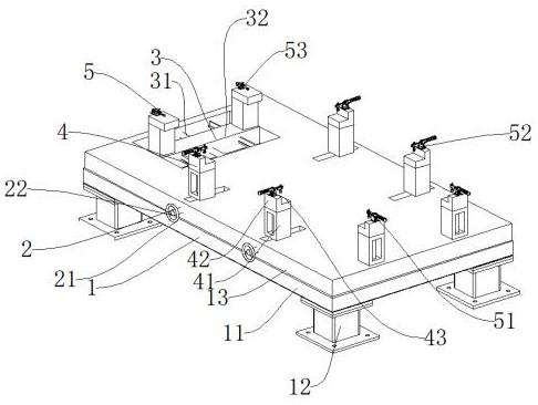
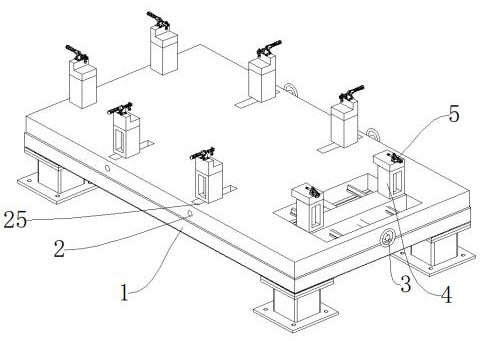
[0044]Such asFigure 1-Figure 6As shown, an adjustable clamping device for processing a safety door frame includes a supporting mechanism 1 for supporting, a clamping mechanism 5 for clamping, and an anti-loosening mechanism 7 for preventing loosening. The supporting mechanism 1 is installed with Horizontal adjustment mechanism 2, one side of the horizontal adjustment mechanism 2 is provided with a longitudinal adjustment mechanism 3, the upper ends of the horizontal adjustment mechanism 2 and the longitudinal adjustment mechanism 3 are both installed with a height adjustment mechanism 4, the upper end of the height adjustment mechanism 4 is installed with a clamping mechanism 5, horizontal adjustment An anti-loosening mechanism 7 is provided between the mechanism 2 and the longitudinal adjustment mechanism 3, and a linkage mechanism 6 is connected to the horizontal adjustment mechanism 2;

[0045]The supporting mechanism 1 includes a supporting base 11, a supporting column 12, and a ba...

Embodiment 2

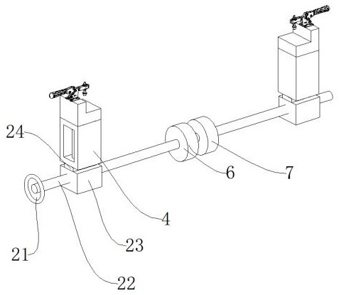
[0053]Such asFigure 7 The difference between this embodiment and embodiment 1 is:

[0054]The linkage mechanism 6 includes a linkage bevel gear 611, a transmission bevel gear 612, and a connecting rod 613. The two linkage bevel gears 611 are respectively mounted on the lateral adjustment screw 22. One side of the linkage bevel gear 611 is connected with a transmission bevel gear 612. The gears 612 are connected by a connecting rod 613. When synchronous rotation adjustment of the lateral adjustment screw 22 is required, the linkage bevel gear 611, the transmission bevel gear 612, and the connecting rod 613 cooperate to make the two lateral adjustment screws 22 rotate synchronously.

[0055]Working principle: According to the specifications of the door frame, adjust the position of the horizontal adjustment slider 23 and the longitudinal adjustment slider 32, so that the second clamp 52 and the ejector clamp 53 can clamp the door frame parts, and then according to the different parts of the...


PUM


Abstract

The invention discloses an adjustable clamping device for safety door frame machining. The adjustable clamping device comprises a supporting mechanism for supporting, clamping mechanisms for clampingand an anti-loosening mechanism for loosening prevention. A transverse adjusting mechanism is mounted on the supporting mechanism. A longitudinal adjusting mechanism is arranged on one side of the transverse adjusting mechanism. Height adjusting mechanisms are mounted at the upper end of the transverse adjusting mechanism and the upper end of the longitudinal adjusting mechanism correspondingly. According to the adjustable clamping device, through the cooperation mode of threads and sliding blocks, the positions of the clamping mechanisms can be adjusted rapidly, thus, the adjustable clampingdevice adapts to door frames of different sizes, and the practicability is improved; through the self-locking property of a screw, the stability during fixing can be guaranteed; a separation shaft isused for switching between two-section structures, thus, manual adjustment and an anti-loosening mode can be switched, and mutual influence is avoided during adjustment; and when fixing is needed, ananti-loosening motor is used for effective loosening prevention, the situation that the positions of the door frames are affected by vibration generated in the machining process is avoided, and the precision is improved.

Description

Technical field[0001]The invention relates to the field of safety door processing, in particular to an adjustable clamping device for processing a safety door frame.Background technique[0002]The subway safety door refers to the glass curtain wall on the platform to surround the subway platform and the train boarding and landing space. When the train arrives, the electric door on the glass curtain wall is opened for passengers to get on and off the train. The main purpose of setting the safety door is to prevent people from falling off the track and causing accidents , To reduce the operating energy consumption of the station’s air conditioning and ventilation system, while reducing the impact of train operating noise and piston wind on the station, providing passengers with a safe and comfortable waiting environment, avoiding delays in operation due to platform accidents, and improving the service level of rail transit. To create the necessary conditions for the rail transit system ...

Claims


Application Information

Patent Timeline
Patent Type & Authority Applications(China)
IPC IPC(8): B25B11/00B23Q3/06
CPCB25B11/00B23Q3/06
Inventor 颜齐
Owner 湖南壹品堂门窗加工有限公司
Why Eureka
Try Eureka