Superimposed cable structure system and morphological analysis method thereof

A form analysis and cable structure technology, which is applied to building components, building structures, and special data processing applications, can solve problems such as large constraints on architectural shapes, achieve good mechanical properties, high-efficiency stress, and broaden the application range.

Pending Publication Date: 2021-01-22
BEIJING INST OF ARCHITECTURAL DESIGN
View PDF0 Cites 6 Cited by
  • Summary
  • Abstract
  • Description
  • Claims
  • Application Information

AI Technical Summary

Problems solved by technology

On the premise of retaining the lightness and transparency of the cable structure, the system can form free and complex geometric surfaces and grids, thereby solving the problem that the existing cable structure system restricts the architectural shape, and greatly broadening the application of the cable structure range; the corresponding morphological analysis method is used to solve the initial state of the proposed superimposed cable structure system, which can meet the architectural modeling requirements, that is, the prestress distribution under the target configuration, and solve the core problem of the engineering application of the system

Method used


Image

  • Superimposed cable structure system and morphological analysis method thereof
  • Superimposed cable structure system and morphological analysis method thereof
  • Superimposed cable structure system and morphological analysis method thereof

Examples


Embodiment 1

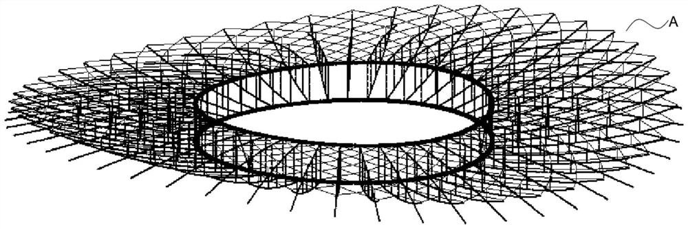
[0062] In this example, Figure 1-Figure 3 The present invention will be described by taking the superimposed cable structure system of saddle-shaped curved surface and rhombus grid as an example (the overall structure shown in A in the figure).

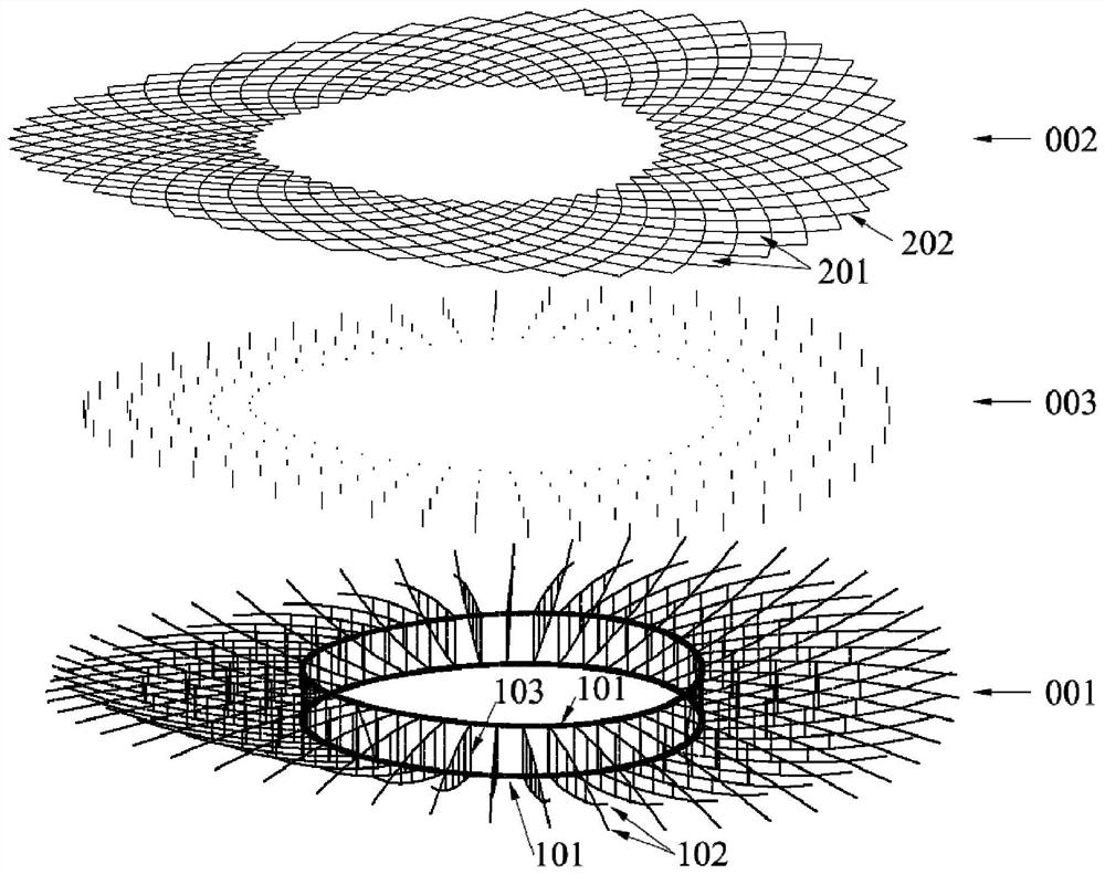
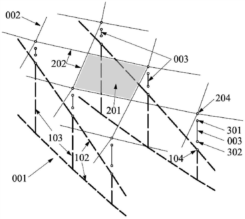
[0063] combine Figure 1 to Figure 3 as shown, figure 1 Shown is a schematic diagram of the composite cable structure system A provided in this embodiment, the upper surface of which is a saddle-shaped surface composed of a series of rhombus grids. figure 2 The composition of the composite cable structure system A is schematically illustrated in the form of an exploded view, which consists of a load-bearing structure 001 , a molding structure 002 and a connecting member 003 . In order to more clearly show the composition of the composite cable structure system A, image 3 A detailed exploded schematic of the system is given.

[0064] The load-bearing structure 001 is located below the composite cable structure system A, providin...

Embodiment 2

[0070] In this example, Figure 4-Figure 6 The present invention will be described by taking the superimposed cable structure system of saddle-shaped curved surface and space triangular grid as an example (the overall structure shown in B in the figure).

[0071] combine Figure 4 to Figure 6 as shown, Figure 4 Shown is the schematic diagram of the superimposed cable structure system B provided in this embodiment, the upper surface of which is a saddle-shaped curved surface, which is composed of a series of spatial triangular grids, and two of the sides of each spatial triangle are straight sides using cables. The third edge is an arc edge with a steel arch. Figure 5 The composition of the composite cable structure system B is schematically illustrated in the form of an exploded view, which consists of a bearing structure 001 , a molding structure 002 and a connecting member 003 . In order to more clearly show the composition of the composite cable structure system B, I...

Embodiment 3

[0078] In this example, Figure 7-Figure 10 The present invention will be described by taking the superimposed cable structure system with slightly convex curved surface and rib ring mesh as an example (the overall structure shown in C in the figure).

[0079] combine Figure 7 to Figure 10 as shown, Figure 7 Shown is the schematic diagram of the composite cable structure system C provided in this embodiment, Figure 8 It is a side view of the composite cable structure system C, the upper surface of which is a slightly convex surface with positive Gaussian curvature, and is arranged in a rib ring grid. Figure 9 The composition of the composite cable structure system C is schematically illustrated in the form of an exploded view, which consists of a bearing structure 001 , a molding structure 002 and a connecting member 003 . In order to more clearly show the composition of the composite cable structure system C, Figure 10 A detailed exploded schematic of the system is g...


PUM


Abstract

The invention relates to the technical field of structural design and analysis of constructional engineering, in particular to a superimposed cable structure system and a morphological analysis methodthereof. According to the system, on the premise that the characteristics of lightness and permeability of the cable structure are reserved, a free and complex geometric curved surface and grids canbe formed, so that the problem that an existing cable structure system greatly restricts building modeling is solved, and the application range of the cable structure is greatly widened; and the corresponding morphological analysis method is used for solving the initial state of the superimposed cable structure system, the prestress distribution meeting the building modeling requirement, namely the target configuration, can be obtained, and the core problem of engineering application of the system is solved.

Description

technical field [0001] The invention relates to the technical field of structural design and analysis of construction engineering, in particular to a superimposed cable structure system and a form analysis method thereof. Background technique [0002] Cable structure is a kind of structural system widely used in large-space public buildings such as stadiums, exhibition halls, theaters, etc. It is composed of cables that can only be tensioned and rods that can be both tensioned and It can be divided into single-layer cable net, cable truss structure, cable dome structure and other forms. Since the cables are made of high-strength materials and are in a state of tension during the load-bearing process of the structure, the force-bearing efficiency is high and there is no problem of component stability. Therefore, its cross-sectional size is much smaller than traditional concrete components and steel components, etc., which can create a very light, Transparent architectural ef...

Claims


Application Information

Patent Timeline
Patent Type & Authority Applications(China)
IPC IPC(8): E04B1/342E04B7/14E04B1/58G06F30/20G06F119/14
CPCE04B1/342E04B1/58E04B7/14G06F30/20G06F2119/14
Inventor 朱忠义白光波陈一邓旭洋张琳王毅崔建华王哲梁宸宇王玮
Owner BEIJING INST OF ARCHITECTURAL DESIGN
Why Eureka
Try Eureka