A kind of intake duct assembly and intake mechanism for automobile

A technology of air intake and assembly, applied in the field of air intake system of motor vehicles, which can solve the problems of large wind resistance, increased air flow resistance, and reduced service life of air filters, so as to improve water removal rate and increase water removal rate and reduce wind resistance

Active Publication Date: 2022-01-18
山东统亚模塑科技实业有限公司
View PDF13 Cites 0 Cited by
  • Summary
  • Abstract
  • Description
  • Claims
  • Application Information

AI Technical Summary

Problems solved by technology

The high-position air intake pipe in the prior art is not effective in filtering dust and rainwater or the wind resistance is too large. Moisture enters the air filter, which will cause the filter paper in the air filter to fail. Once the filter paper of the air filter is attached by rainwater, the filter paper will lose its filtration As a result, the resistance of the airflow will be increased, which will affect the intake air volume of the entire intake system, resulting in insufficient engine power, resulting in a reduction in the service life of the air filter, and thus affecting the service life of the engine.
If the air filter fails, rainwater will enter the engine through the rubber pipe, causing water to enter the engine and causing damage to the engine
[0004] When the engine of a heavy truck is running, it inhales about 20m per minute 3 -30m 3 The air, now with the development of the truck to the high-speed and heavy-duty direction, the air intake flow reaches 25m 3 / min and above heavy-duty trucks, the pre-filter device in the prior art or its simple combination can no longer meet the requirements of use
[0005] With the upgrading of light-duty vehicle National V vehicle technology, higher requirements are placed on the air intake system. The existing air intake assembly cannot meet the requirements of key performance indicators such as dust removal efficiency, water removal efficiency, and air intake resistance. Increased requirements

Method used


Image

  • A kind of intake duct assembly and intake mechanism for automobile
  • A kind of intake duct assembly and intake mechanism for automobile
  • A kind of intake duct assembly and intake mechanism for automobile

Examples


Embodiment 1

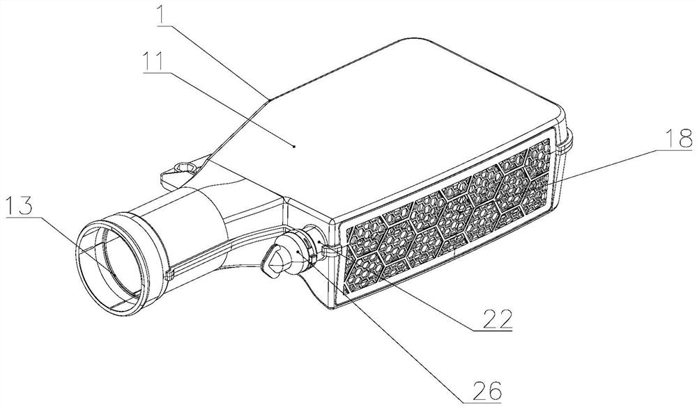
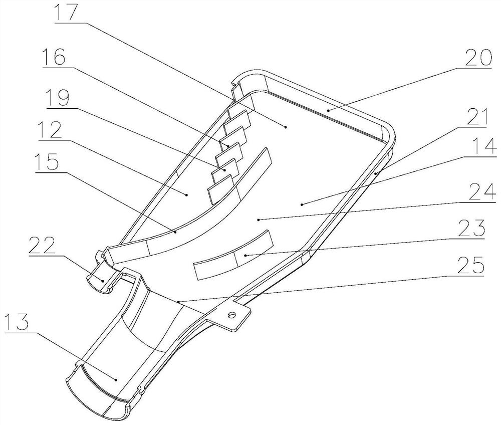
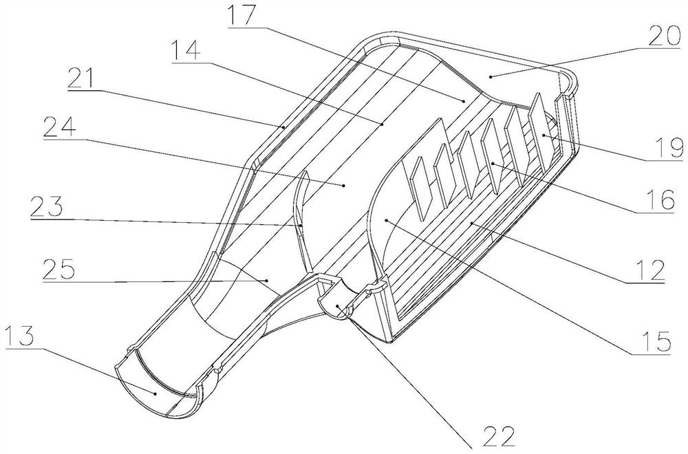
[0056] refer to Figure 1-3 , the embodiment of the present application discloses an air inlet assembly 1 for automobiles, which includes an air inlet casing 11, a first air inlet 12 is arranged on the side wall of the air inlet casing 11, and the air inlet casing The bottom wall of 11 is provided with air outlet 13, and air inlet casing 11 forms air inlet cavity 14, and the first separating plate 15 and separating grid 16 are arranged in the air inlet cavity 14, and first separating plate 15 separates from first air inlet 13 The bottom bends inwards and extends upwards, the top of the first separation plate 15 forms the second air inlet 17 with the inner wall of the air inlet casing 11, and the separation grid 16 is inclined inward from the top of the first air inlet 12 and arranged downwards Extending, the separation grid 16 is arranged outside the second air inlet 17 , and the bottom end of the separation grid 16 is not higher than the top end of the first separation plate ...

Embodiment 2

[0073] Test the sample of the rapid production assembly after the completion of the intake port design stage, the intake port assembly 1 of the preferred embodiment, the inside of the intake port RP sample S = 11155mm 2 ;S outer = 16377mm 2 , wherein, the inside of S is the effective air intake area of ​​the separation grid 16, and the outside of S is the effective opening area of ​​the porous isolation cover 18.

[0074] Compared with the air inlet assembly 1, the first air inlet 12 is provided for the air inlet housing, the first air inlet 12 is directly equipped with a separation grid 16, and the downstream of the first air inlet 12 in the air inlet chamber 14 is set The first separation plate 15, that is, the difference between the air inlet assembly 1 and the comparison air inlet assembly 1 includes: the separation grid 14 of the air inlet assembly 1 is installed on the first air inlet 12, while the comparison air inlet The separation grille 14 of the assembly 1 is insta...

Embodiment 3

[0089] refer to Figure 5-7 The difference between this embodiment and Embodiment 1 is that the first miscellaneous outlet 27 is arranged on the first side wall 28 of the air inlet casing 11, close to the bottom wall of the air inlet casing 11, and the first miscellaneous outlet The port 27 and the first air inlet 12 are arranged on opposite sides of the first separation plate 15, and a resonant cavity 29 is arranged inside the first separation plate 15; a second separation plate 23 is also arranged in the air intake chamber, and the second separation plate 23 Arranged above the air outlet 13 , the second separation plate 23 includes a front separation plate, a middle separation plate and a rear separation plate connected in sequence, and the opening between the front separation plate and the rear separation plate faces the air outlet 13 . The second separation plate 23 performs secondary removal of impurities such as water in the airflow, and the moisture in the airflow hitti...


PUM


Abstract

The application discloses an air intake port assembly for an automobile and an air intake mechanism, which belong to the technical field of the air intake system of a motor vehicle. The intake port assembly for automobiles includes an intake port housing, the side wall of the intake port case is provided with a first air inlet, the bottom wall of the intake port case is provided with an air outlet, and the intake port case forms an intake cavity , a first separation plate and a separation grille are arranged in the air inlet cavity, the first separation plate is bent inward from the bottom of the air inlet and extends upward, and the top of the first separation partition and the inner wall of the air inlet shell form a second air inlet , the separation grille is inclined inward from the top of the air inlet and extends downward, the separation grille is arranged on the outside of the second air inlet, and the bottom end of the separation grille is not higher than the top of the first separation partition. The automobile air intake assembly of the present application has high filtration and impurity removal efficiency, small wind resistance, low energy consumption, and low noise; the air intake assembly of the air intake mechanism and the air filter do not need to be connected by a bellows, and the preparation cost low, and tight assembly tolerances.

Description

technical field [0001] The application relates to an air inlet assembly and an air intake mechanism for automobiles, belonging to the technical field of air intake systems of motor vehicles. Background technique [0002] The car needs air to continuously enter the engine during driving. In order to prevent sand and dust from entering the engine, the air intake system of the car includes a high air intake pipe, which is connected to the air filter through a bellows rubber tube. The air filter is installed on the front of the car through The rubber pipe is connected with the engine. The air entering the engine generally enters the high intake pipe first, then enters the air filter through the corrugated rubber tube, and then enters the engine after being filtered by the air filter. [0003] As an important part of the intake system, the high-position intake pipe plays the role of dust and water removal, which is equivalent to the primary filter in the intake system. The high...

Claims


Application Information

Patent Timeline
Patent Type & Authority Patents(China)
IPC IPC(8): F02M35/022F02M35/08F02M35/10F02M35/16B60K13/02
CPCF02M35/0226F02M35/08F02M35/088F02M35/10006F02M35/16B60K13/02
Inventor 朱庆凯
Owner 山东统亚模塑科技实业有限公司
Why Eureka
Try Eureka