
Phase change type quenching heat exchanger

A rapid cooling heat exchanger and phase change technology, applied in the direction of heat exchanger type, heat exchanger shell, indirect heat exchanger, etc., can solve the problems of limited production capacity, limited flow of cooling medium in and out, and large impact on strength, etc., to achieve The effect of increasing production capacity and guaranteeing strength

Pending Publication Date: 2021-01-22
THE CHALLENGE PETROCHEM MACHINERY CORP
View PDF0 Cites 1 Cited by
  • Summary
  • Abstract
  • Description
  • Claims
  • Application Information

AI Technical Summary

Problems solved by technology

[0004] With the gradual increase in production capacity requirements, the volume of the quenching heat exchanger is also increasing. However, the inventors found that if the shell, inlet joints and outlet joints and other modules are expanded in equal proportions, it is easy to cause local strength to decrease, which cannot meet the requirements. Standard requirements, especially the position of the inlet joint and outlet joint, the excessive opening of the side wall of the shell has a great impact on its strength. The existing quenching heat exchanger only has one inlet on the bottom side and the top side of the shell. and an export, the size of the import and export limits the capacity increase
In addition, even if multiple inlets and multiple outlets are respectively provided in the axial direction on the bottom side and the top side of the shell, for the same longitudinal section of the shell, the flow rate of the cooling medium is still relatively restricted.

Method used


Image

  • Phase change type quenching heat exchanger
  • Phase change type quenching heat exchanger
  • Phase change type quenching heat exchanger

Examples


Embodiment Construction

[0025] The present invention will be described in detail below in conjunction with specific embodiments and accompanying drawings.

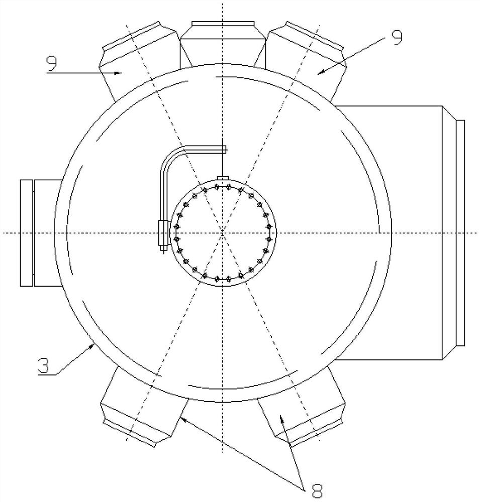
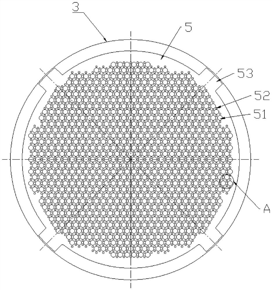
[0026] The phase change quenching heat exchanger of the present embodiment, such as Figure 1 to Figure 4 As shown, it includes an inlet tube box 1, a front tube plate 2, a shell 3, a plurality of heat exchange tubes 4, a support plate 5, a rear tube plate 6 and an outlet tube box 7. The shell 3 is cylindrical and arranged horizontally, and the front The tube sheet 2 and the rear tube sheet 6 are respectively fixed to the two ends of the shell 3 so as to enclose the shell side space. The inlet tube box 1 is fixed on the front tube sheet 2 and both of them jointly enclose the front tube pass space, and the outlet tube box 7 is fixed on the rear tube sheet 6 and both of them jointly enclose the rear tube pass space. Both ends of the plurality of heat exchange tubes 4 are fixed to the front tube sheet 2 and the rear tube sheet 6 respectively, and a...


PUM


Abstract

The invention relates to the technical field of petrochemical equipment, and particularly relates to a phase change type quenching heat exchanger. The phase change type quenching heat exchanger comprises an inlet pipe box, a front pipe plate, a shell, a plurality of heat exchange pipes, a supporting plate, a rear pipe plate and an outlet pipe box. Due to the fact that heat exchange at the positionclose to the front pipe plate is intense, a plurality of bubbles are formed by vaporization of a cooling medium; at least two inlet connectors and at least two outlet connectors are arranged on the section, close to the front pipe plate, of the shell; every two inlet connectors are symmetrically distributed on the two sides of the bottom of the shell relative to the longitudinal section parallelto the axial direction of the shell; and every two outlet connectors are symmetrically distributed on the two sides of the top of the shell relative to the longitudinal section parallel to the axial direction of the shell. The requirement for large flow of the cooling medium can be met, more cooling media flow in, more steam is discharged, the productivity is improved, the single inlet connector or outlet connector does not need to be opened too large, and the strength of the shell is guaranteed. Heat exchange close to the rear portion is gentle, and the inlet connectors and the outlet connectors can be connected with the shell in a common manner.

Description

technical field [0001] The invention relates to the technical field of heat exchangers in the petrochemical industry, in particular to a phase change quenching heat exchanger. Background technique [0002] Heat exchanger is an indispensable equipment to realize heat exchange and transfer in the chemical production process, and shell-and-tube heat exchanger is the most widely used heat exchange equipment in industry, such as ethylene cracking furnace, hydrocarbon raw materials at high temperature, generate carbon Chain scission or dehydrogenation reaction to produce ethylene, propylene, etc., and by-products such as butene, butadiene and other olefins and pyrolysis gasoline, diesel, fuel oil and other products. The chemical thermodynamic state of these components is very unstable at the cracking temperature. The longer the residence time in the high temperature zone, the more secondary reactions and the lower the olefin yield. In order to increase the yield of the target pr...

Claims


Application Information

Patent Timeline
IPC IPC(8): F28D7/16F28F9/013F28F9/02F28F9/26F28F13/06F28F19/00
CPCF28D7/16F28F9/0131F28F9/0229F28F9/26F28F13/06F28F19/00
Inventor 黄嗣罗刘恒林进华雷小娣李辉林
Owner THE CHALLENGE PETROCHEM MACHINERY CORP
Learn More