Electronic detonator front-end control circuit

A technology for controlling circuits and electronic detonators, which is applied in weapon accessories, fuzes, offensive equipment, etc., can solve the problems of endangering personal and property safety, electronic detonator detonation error, signal distortion, etc., and achieve the effect of eliminating the danger of failure and speeding up the wiring efficiency

Pending Publication Date: 2021-01-22
洛阳正硕电子科技有限公司
View PDF5 Cites 4 Cited by
  • Summary
  • Abstract
  • Description
  • Claims
  • Application Information

AI Technical Summary

Problems solved by technology

[0005] The purpose of the present invention is to provide a front-end control circuit of an electronic detonator to solve the problem that when the electronic detonator receives a long-distance transmission signal, the signal is disturbed and distorted, which may easily cause the electronic detonator to detonate incorrectly or fail to proceed smoothly, and even endanger the safety of personal property.

Method used


Image

  • Electronic detonator front-end control circuit
  • Electronic detonator front-end control circuit

Examples


Embodiment 1

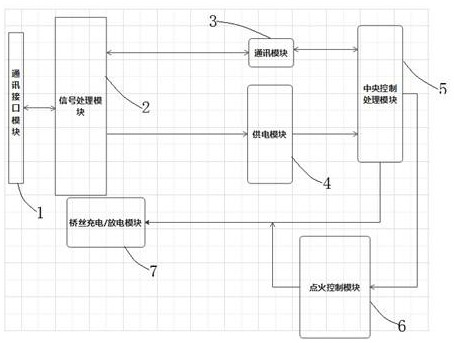
[0030] Example 1 please refer to figure 1 An embodiment shown is a front-end control circuit of an electronic detonator, including a communication interface module 1, a signal processing module 2, a communication module 3, a power supply module 4, a central control processing module 5, an ignition control module 6 and bridge wire charging / discharging Module 7, of which:

[0031] One end of the communication interface module 1 is connected to an external detonator, and the other end is connected to one end of the signal processing module 2, and the communication interface module 1 realizes communication and current flow between the above-mentioned other modules and the external detonator;

[0032] The other end of the signal processing module 2 is respectively connected to one end of the communication module 3 and the power supply module 4, and the communication interface module 1 prevents the current with a frequency between 50MHz-100 MHz from interfering with the communicatio...

Embodiment 2

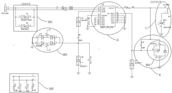
[0039] On the basis of the above-mentioned embodiment 1, please refer to the embodiment 2 figure 2 In one embodiment shown, the signal processing module 2 includes an ESD circuit 201 and an EMI circuit 202, and the ESD circuit and the EMI circuit are respectively connected in parallel with the P / N lines in the circuit.

[0040] Preferably, the EMI circuit 202 includes a capacitance group of two capacitive elements connected in series, a resistance group of two series resistance elements and a P / N line connected to the control circuit, and the capacitance group is connected in parallel to the P / N line , the resistance group is connected in parallel to the P / N line, wherein:

[0041] The resistive element is 4.7M ohms, and the capacitive element is 1nF.

[0042] Preferably, the ESD circuit 201 includes an ESD electrostatic impedance device D1, an ESD electrostatic impedance device D2 and a P / N line connected to the control circuit, and the ESD electrostatic impedance device D1...

Embodiment 3

[0046] On the basis of the above embodiments, Embodiment 3 shows an embodiment, the power supply module 4 is provided with a rectification circuit 401, the rectification circuit includes four rectification diodes, and every two rectification diodes are connected in series to form two groups The rectifier bridge, the two sets of rectifier bridges form a full bridge circuit.

[0047] The power supply module 4 is provided with a rectification circuit 401. The rectification circuit includes four rectification diodes. Every two rectification diodes are connected in series to form two sets of rectification bridges. The two sets of rectification bridges form a full bridge circuit. This circuit is a rectification circuit that converts alternating current into stable Direct current, when communicating with the external detonator, the detonator can connect the two communication wires regardless of the front and back, and can connect them arbitrarily, which speeds up the wiring efficiency...


PUM


Abstract

The invention discloses an electronic detonator front-end control circuit. The control circuit is integrated on a front-end control chip in an electronic detonator and used for detonation control workof the electronic detonator, a signal processing module comprises an ESD circuit and an EMI circuit which jointly form a common-mode interference protection circuit to effectively prevent the detonator from being damaged by current interference with the frequency of 50 M-100 MHz, and even the electronic detonator is prevented from being mistakenly detonated; and in addition, an ignition control module is further arranged and serves as the last verification and switch before initiation, initiation can be achieved only through verification of the ignition control module, the ignition control module is further provided with a PMOS switch tube, the current protection effect is achieved, a layer of insurance is added for initiation work, a power supply module does not distinguish positive andnegative wiring, the wiring efficiency of the electronic detonator is improved, and the electronic detonator front-end control circuit effectively protects the accuracy of an electric signal, reducesthe distortion of the electric signal, ensures the smooth and accurate initiation of the electronic detonator, and protects the personal and property safety.

Description

technical field [0001] The invention relates to the technical field of electronic detonators, in particular to a front-end control circuit of an electronic detonator. Background technique [0002] Explosives are substances that can burn violently (that is, explode) in a very short period of time, and can explode by their own energy under the action of a certain amount of external energy. Under normal circumstances, the chemical and physical properties of explosives are stable, but regardless of whether the environment is sealed or not, the amount of charge, or even in the case of zero oxygen supply from the outside world, as long as there is strong energy (provided by the detonator) to stimulate, the explosives will be released to the outside world. Carry out stable detonation type work. When the explosive explodes, it can release a large amount of heat energy and generate high-temperature and high-pressure gas, which can damage, throw, and compress the surrounding material...

Claims


Application Information

Patent Timeline
Patent Type & Authority Applications(China)
IPC IPC(8): F42C19/12
CPCF42C19/12
Inventor 张国栋周军冯华邱刚刘振辉黄楚华
Owner 洛阳正硕电子科技有限公司
Why Eureka
Try Eureka