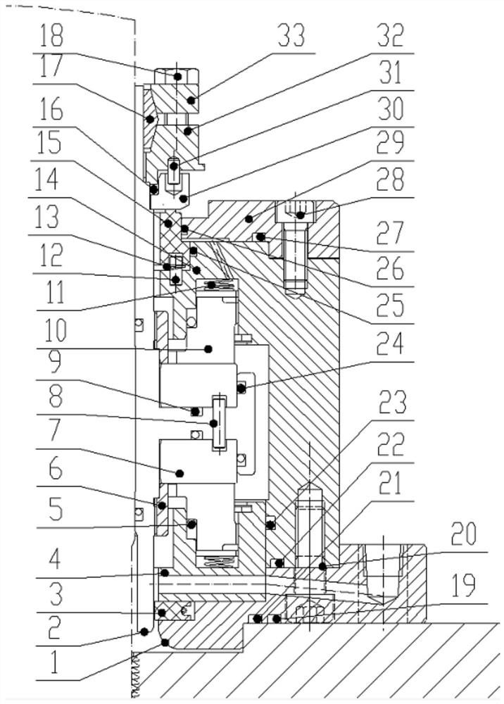
Dry gas sealing device of nuclear fuel circulating pump
A dry gas sealing and circulating pump technology, which is applied to the components of the pumping device for elastic fluid, the sealing of the engine, the fuel element of the reactor, etc. The effect of good durability, less nuclear radiation and long service life
- Summary
- Abstract
- Description
- Claims
- Application Information
AI Technical Summary
Problems solved by technology
Method used
Image
Examples
Embodiment 1
[0039] Such as figure 1 As shown, the present invention is a dry gas sealing device for a nuclear fuel circulation pump, which includes a shaft sleeve 2 sleeved on a rotating shaft, a spring seat 4, a safety sealing ring and a sealing chamber cavity 14, and the shaft sleeve 2 passes through the end cover 1. The spring seat 4 and the sealing chamber body 14, the sealing chamber body 14 includes the moving ring 7 and the static ring 10, the outer side of the sleeve 2 is provided with an annular protrusion, the static ring 10 and the moving ring 7 Set symmetrically with annular protrusions, static rings 10 are arranged on both sides of the moving ring 7, the moving ring 7 is fixedly connected with the bushing 2, a spring seat 4 is provided at one end of the static ring 10, and the spring seat 4 and the The sealed cavity cavity 14 is flexibly connected,
[0040] The safety sealing ring includes a safety sealing static ring 15 and a safety sealing dynamic ring 30, the safety sealing...
Embodiment 2
[0043] Such as figure 1 As shown, this embodiment is based on Embodiment 1, the drive ring 7 includes a lower end drive ring 32 and an upper end drive ring 33, the safety sealing dynamic ring 30 is connected to the lower end drive ring 32 through a second anti-rotation pin 31, the The second anti-rotation pin 12 is connected with the lower end drive ring 32, and the lower end drive ring 32 is connected with the upper end drive ring 33 through the wedge ring 17, and one end of the upper end drive ring 33 is provided with a locking screw 18; the lower end of the wedge ring 17 The inclined surface cooperates with the lower end driving ring 32, and the upper end inclined surface cooperates with the upper end driving ring 33. The lower end driving ring 32 is provided with some screw holes, and the upper end driving ring 33 is connected with the lower end driving ring 32 by bolts.
[0044] A sealing ring 5 is arranged between the end cover 1 and the static ring 10, and a sealing rin...
Embodiment 3
[0053] Such as figure 1 As shown, this embodiment is based on Embodiments 1 and 2. The end surface of the moving ring 7 is processed with a fluid dynamic pressure groove. Based on the principle of dynamics, the seal realizes non-contact operation, and at the same time realizes the blocking of the medium, ensuring zero leakage of the nuclear radiation medium to the external environment.
[0054] Working process: the sealing gas enters the safety seal through the small hole, and the pressure acts on the middle step of the safety seal static ring 15. When the force of the pressure on the middle step is greater than the elastic force of the first spring 11, the safety seal static ring 15 will be pushed down Push the compression spring to separate from the safety seal moving ring 30, and open the circulation channel for the leakage gas of the main seal on the atmosphere side, and the seal works normally.
[0055] When encountering an emergency, the pressure of the sealing gas decr...
PUM
 Abstract
Description
Claims
Application Information
 - R&D
- Intellectual Property
- Life Sciences
- Materials
- Tech Scout
- Unparalleled Data Quality
- Higher Quality Content
- 60% Fewer Hallucinations
Browse by: Latest US Patents, China's latest patents, Technical Efficacy Thesaurus, Application Domain, Technology Topic, Popular Technical Reports.
© 2025 PatSnap. All rights reserved.Legal|Privacy policy|Modern Slavery Act Transparency Statement|Sitemap|About US| Contact US: help@patsnap.com

