
Resonant transformer

A technology of resonant transformer and skeleton, applied in the direction of transformer, variable transformer, transformer/inductor components, etc., can solve the problems of difficult to control leakage inductance, large parasitic capacitance, unfavorable stable operation and efficiency of transformer, etc., to achieve convenient production and operation , reduce the capacitance, the effect of conducive to stable operation

Pending Publication Date: 2021-01-26
WURTH ELECTRONICSCHONGQING +1
View PDF0 Cites 0 Cited by
  • Summary
  • Abstract
  • Description
  • Claims
  • Application Information

AI Technical Summary

Problems solved by technology

[0006] The present invention aims to propose a resonant transformer, which is used to solve the problems in the prior art that the leakage inductance is not easy to control and the parasitic capacitance is large, which is not conducive to the stable operation and efficiency of the transformer

Method used


Image

  • Resonant transformer
  • Resonant transformer
  • Resonant transformer

Examples


Embodiment Construction

[0031] The following will clearly and completely describe the technical solutions in the embodiments of the present invention with reference to the accompanying drawings in the embodiments of the present invention. Obviously, the described embodiments are only some, not all, embodiments of the present invention.

[0032] Such as Figure 4 to Figure 10 as shown, Figure 4 It is shown as a structural schematic diagram of the resonant transformer in the present invention. Figure 5 shown as Figure 4 Schematic diagram of the explosion structure. Figure 6 It is a schematic structural diagram of the first embodiment of the resonant transformer in the present invention. Figure 7 It is a schematic structural diagram of the second embodiment of the resonant transformer in the present invention. Figure 8 It is a schematic structural diagram of the third embodiment of the resonant transformer in the present invention. Figure 9 It is a schematic structural diagram of the fourth ...


PUM


Abstract

The invention discloses a resonant transformer which comprises a magnetic core assembly, a partition plate, a framework assembly, a primary winding and a secondary winding. The framework assembly comprises two hollow frameworks arranged in parallel, the magnetic core assembly comprises two magnetic cores, each magnetic core comprises two magnetic arms and is of a U-shaped structure as a whole, themagnetic arms of the magnetic cores are inserted into the corresponding frameworks to form the state that the two magnetic cores are symmetrically arranged on the two sides of the framework assembly,and a plurality of wire grooves are formed in the frameworks. The primary winding and the secondary winding are respectively wound in the wire grooves; the state that the primary winding and the secondary winding are respectively wound on the magnetic core assembly is formed; and the partition plate is arranged between the two frameworks, and the two ends of the partition plate abut against the magnetic core assemblies respectively. Various combinations are adopted to realize various leakage inductors, the structure is simple, and the production operation is convenient. The skeleton convex ribs are added, so that the insulation distance between the copper sheets and the distance between the copper sheet winding and the primary winding are ensured, and the production efficiency and reliability are improved. Stable operation of the circuit is facilitated, and circuit performance is improved.

Description

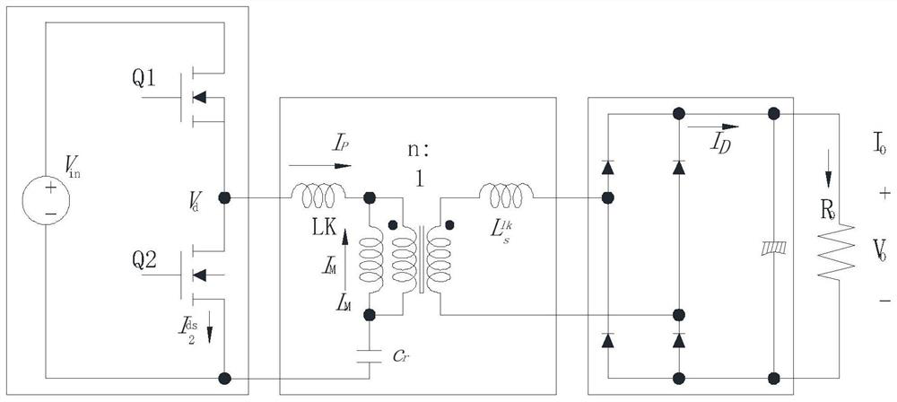
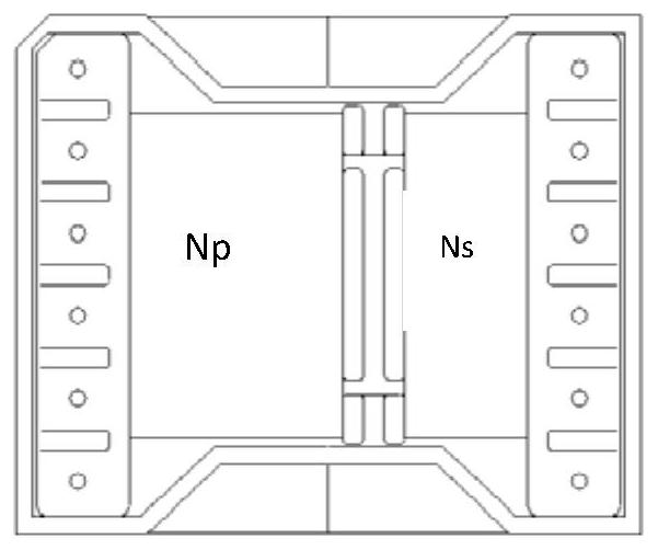
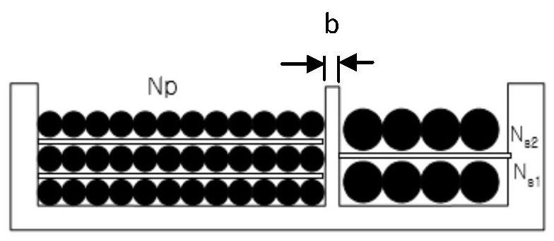
technical field [0001] The invention relates to the technical field of resonant transformers, in particular to a resonant transformer. Background technique [0002] The LLC resonant transformer circuit usually consists of 3 parts: a square wave generator, a resonant network, and a rectifier network. Such as figure 1 as shown, figure 1 It is shown as a circuit topology diagram of a resonant transformer in the prior art. Wherein, the square wave generator generates the square wave voltage Vd by alternately driving the switches Q1 and Q2 with a 50% duty cycle each time switching. The resonant network includes the excitation inductance Lm of the transformer, the leakage inductance Lk and the resonant capacitor Cr, so it is called LLC. The rectification network adjusts the alternating current through rectifying diodes and capacitors, and outputs a direct current voltage. [0003] The current LLC resonant transformer usually winds the corresponding primary coil Np and seconda...

Claims


Application Information

Patent Timeline
Patent Type & Authority Applications(China)
IPC IPC(8): H01F29/12H01F27/28H01F27/30H01F27/32H01F27/34
CPCH01F29/12H01F27/306H01F27/324H01F27/2847H01F27/34
Inventor 刘修佳李祖佳袁红梅吴梦辉
Owner WURTH ELECTRONICSCHONGQING
Learn More