

Vapor chamber, vapor chamber manufacturing method and electronic equipment
A manufacturing method and vapor chamber technology, which is applied to the structural parts of electrical equipment, cooling/ventilation/heating transformation, electrical components, etc., can solve problems such as high manufacturing costs, defective products, and complicated procedures of vapor chambers, and achieve processing Low cost, high production yield, and the effect of reducing product defects
- Summary
- Abstract
- Description
- Claims
- Application Information
AI Technical Summary
Problems solved by technology
Method used
Image

Examples
Embodiment 1
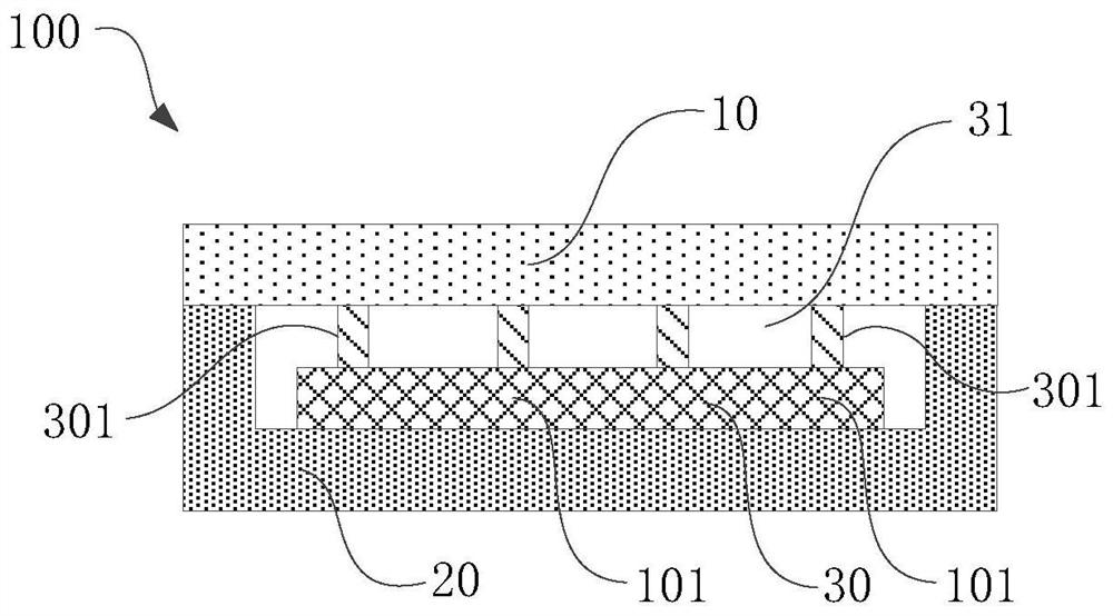
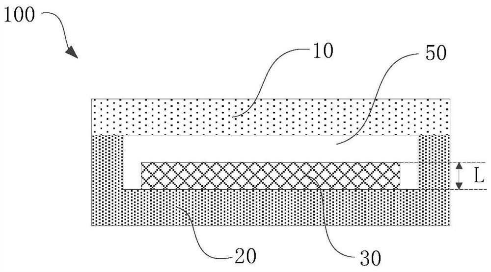
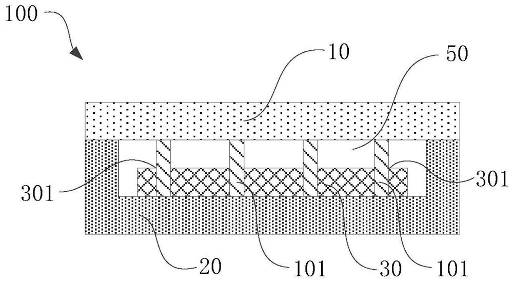
[0056] The embodiment of the present application provides a vapor chamber 100, which is used to contact the heat-generating device to dissipate heat from the heat-generating device. Refer to figure 1 As shown, the vapor chamber 100 may include: a first shell 10 , a second shell 20 and a capillary structure 30 , the adhesive connection between the first shell 10 and the second shell 20 encloses a closed accommodating cavity 50 , and the accommodating cavity 50 is provided with a working medium (ie, a working medium). The capillary structure 30 is located in the accommodating cavity 50 , and a side of the capillary structure 30 facing the second housing 20 is fixed to the second housing 20 .
[0057] In the embodiment of the present application, the adhesive connection between the first shell 10 and the second shell 20 is compared to the way of brazing in the prior art to fix the first shell 10 and the second shell 20, The embodiment of the present application cancels the high-...
Embodiment 2
[0068] On the basis of the first embodiment above, refer to Figure 4 As shown, the embodiment of the present application provides a method for manufacturing a vapor chamber, which may include:
[0069] S101 : At least provide a first housing 10 , a second housing 20 and a capillary structure 30 .
[0070] Wherein, the first housing 10 and the second housing 20 may enclose a closed accommodation chamber 50 , and the capillary structure 30 is located in the accommodation chamber 50 .
[0071] The embodiment of the present application does not limit the materials of the first housing 10 and the second housing 20 , for example, they may be copper or copper alloy.
[0072] Wherein, in a possible implementation manner, the capillary structure 30 may be any one or more of metal mesh, foam metal or sintered metal powder.
[0073] When the capillary structure 30 can be any one or more of metal mesh, foam metal or sintered metal powder, the pore diameter of the capillary structure 30...
Embodiment 3
[0121] An embodiment of the present application provides an electronic device 200, which may at least include a heat generating device and the vapor chamber 100 in the first embodiment above, wherein the heat generating device is in contact with the outer surface of the chamber 100 so that heat can be generated through the chamber 100 The heat emitted by the device is dissipated.
[0122] Wherein, in the embodiment of the present application, the heat generating device may be a chip, or the heat generating device may also be a battery or a circuit board or the like.
[0123] The electronic device 200 provided by the embodiment of the present application may include, but not limited to, a mobile phone, a tablet computer, a notebook computer, an ultra-mobile personal computer (ultra-mobile personal computer, UMPC), a handheld computer, a walkie-talkie, a netbook, a point of sale (Point of sales , POS) machine, personal digital assistant (personal digital assistant, PDA), wearabl...
PUM
 Abstract
Description
Claims
Application Information