Method for producing a vehicle traction battery

A technology for power batteries and vehicles, applied in battery/battery traction, batteries, manufacturing tools, etc., which can solve problems such as incorrect placement of battery modules and damage to battery module performance

Active Publication Date: 2021-01-26
AUDI AG
View PDF12 Cites 0 Cited by
  • Summary
  • Abstract
  • Description
  • Claims
  • Application Information

AI Technical Summary

Problems solved by technology

This can lead to incorrect positioning of the battery module in the batte

Method used


Image

  • Method for producing a vehicle traction battery
  • Method for producing a vehicle traction battery
  • Method for producing a vehicle traction battery

Examples


Embodiment Construction

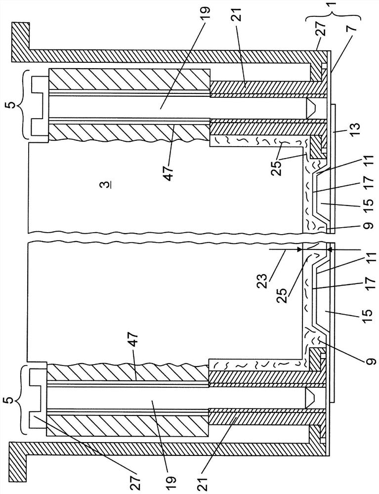
[0018] exist figure 1 , the traction battery of an electric vehicle is shown in a roughly simplified side sectional view. The traction battery has a pot-shaped or box-shaped battery housing 1 , in which a rectangular battery module 3 is accommodated, which consists of individual cells (not shown). The battery module 3 is mounted on the housing bottom 7 of the battery housing 1 by means of a fastening unit 5 . Such as figure 1 It is further shown that the housing bottom 7 has a housing bottom base 9 and a cooling embossment 11 which is raised from the housing bottom base by a pressing height in the direction of the housing interior. The cooling emboss 11 together with the lower cover part 13 delimits a coolant channel 15 which is a component of the external vehicle cooling system. The upper side of the cooling pressing part 11 is in figure 1 A contact contour 17 is formed in , on which the battery module 3 is placed via an insulating layer of thermally conductive paste.

...


PUM


Abstract

The invention relates to a method for fitting at least one battery module (3) into a battery housing (1) of a traction battery of a vehicle, in which, in a delivery process step, the battery module (3) is introduced into the battery housing (1) in a robot-controlled manner via a delivery path and by means of a delivery force (F), and until reaching an assembled position (A) in which the battery module (3) is in the correct position on a contact contour (17) of a housing base (7) of the battery housing (1), and in a securing process step, the correctly positioned battery module (3) is secured in the battery housing (1). According to the invention, the delivery process step is monitored by a monitoring unit (40), which detects an actual delivery path (zist) and an actual delivery force (Fist) during the delivery process step, and evaluates whether the delivery process step is being carried out error-free or not on this basis.

Description

technical field [0001] The invention relates to a method according to the preamble of claim 1 for fitting at least one battery module into a battery housing of a traction battery of a vehicle and a method according to claim 8 for carrying out the Methods for robotic facilities. Background technique [0002] A traction battery of an electric vehicle has single cells which are combined as a battery pack in a square battery module. A plurality of such battery modules can be arranged in a battery housing which can be arranged in the vehicle. The battery modules arranged in the battery housing can be cooled with a cooling system in order to achieve better operating performance. The cooling system can be, for example, a coolant circuit of the vehicle into which coolant channels in the housing bottom of the battery housing open. In order to achieve good thermal conductivity between the battery module and the bottom of the housing, the heat-insulating air gap between the battery ...

Claims


Application Information

Patent Timeline
IPC IPC(8): H01M50/249B25J9/16B60K1/04B60L50/64H01M50/204H01M50/264
CPCH01M2220/20B60K1/04B60K2001/0438B60K2001/006B60L50/64Y02T10/70Y02E60/10Y02P70/50H01M50/204H01M50/249H01M50/264
Inventor F·舍恩贝格尔T·朗格R·福尔纳尔斯
Owner AUDI AG
Why Eureka
Try Eureka