Long ball screw auxiliary supporting device for diamond cone numerical control lathe

A technology of CNC lathes and ball screws, which is applied in the direction of feeding devices, metal processing equipment, metal processing machinery parts, etc., can solve the problems of affecting the use of sliders, reducing work efficiency, and debris splashing, so as to shorten the service life and improve Mobile performance, avoiding the effect of excessive gravity

Pending Publication Date: 2021-01-29
苏州志纳精密科技有限公司
View PDF0 Cites 0 Cited by
  • Summary
  • Abstract
  • Description
  • Claims
  • Application Information

AI Technical Summary

Problems solved by technology

[0003] 1. In the existing technology, the span of many large CNC lathes in many enterprises is greater than 4 meters. The ball screw sags due to its own gravity and deforms the screw rod, resulting in violent vibration of the ball screw during movement. , not only increases the motion noise, but also damages the screw and support bearings, greatly shortens the service life of the screw and support bearings, thus greatly reducing the motion accuracy and machining accuracy
[0004] 2. During the processing of the numerical control garage, there will be debris splashed on the slide rail, which makes the slide block easy to be stuck during operation, resulting in scratches on the slide rail, so that the surface of the slide rail is no longer smooth and jammed. If the living debris is not cleaned out in time, it will only make the scratches on the slide rails and sliders more and more serious, greatly reducing the service life of the slide rails and sliders, and will also affect the use of the sliders during the moving process, greatly Reduced work efficiency

Method used


Image

  • Long ball screw auxiliary supporting device for diamond cone numerical control lathe
  • Long ball screw auxiliary supporting device for diamond cone numerical control lathe
  • Long ball screw auxiliary supporting device for diamond cone numerical control lathe

Examples


Embodiment Construction

[0024] The following will clearly and completely describe the technical solutions in the embodiments of the present invention with reference to the accompanying drawings in the embodiments of the present invention. Obviously, the described embodiments are only some, not all, embodiments of the present invention. Based on the embodiments of the present invention, all other embodiments obtained by persons of ordinary skill in the art without creative efforts fall within the protection scope of the present invention.

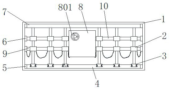
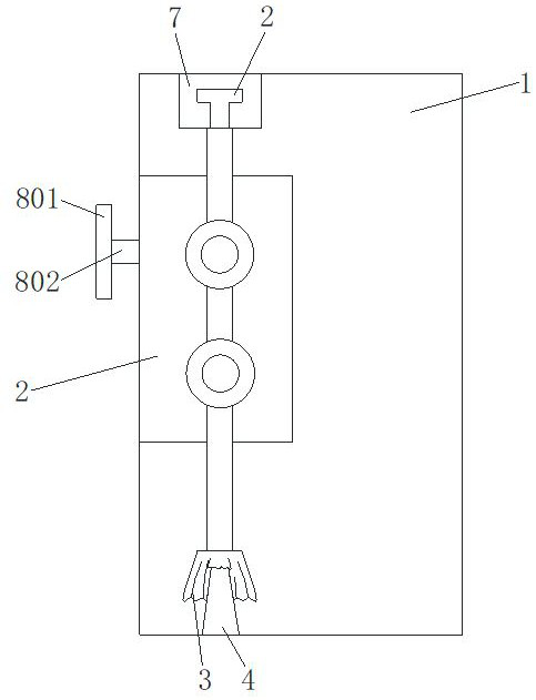
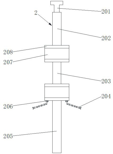
[0025] see Figure 1-4 As shown, the present invention is a long ball screw auxiliary support device for a diamond cone CNC lathe, including a main body frame 1, a support assembly 2, a cleaning assembly 3, a first connecting block 5 and a second slide rail 7, and a support assembly 2 There are six cleaning assemblies 3, four first connecting blocks 5 and four second connecting blocks 6, the front side of the top of the inner wall of the main frame 1 is fixedly con...


PUM


Abstract

The invention discloses a long ball screw auxiliary supporting device for a diamond cone numerical control lathe and relates to the technical field of mechanical devices. The long ball screw auxiliarysupporting device comprises a main body frame, a supporting assembly, a cleaning assembly, a first connecting block and a second slide rail, wherein the second slide rail is fixedly connected to thefront side of the top of the inner wall of the main body frame, a first slide rail is fixedly connected to the front side of the bottom of the inner wall of the main body frame, a threaded rod and a supporting bearing are successively connected to two sides of the inner wall of the main body frame up and down, a case is arranged in a center position of the main body frame, the case is fixedly connected to the supporting bearing and the threaded rod, the top of the supporting assembly is slidably connected to the middle of the inner side of the second slide rail, and the cleaning assembly fixedly connected to the bottom of the supporting assembly is slidably connected to the outer side of the first slide rail. By arranging the supporting assembly and the cleaning assembly, problems that a ball screw is prone to drooping and shaking severely due to self gravity and the slide rail is worn severely as machining fragments will be clamped in the slide rail and the slide block are solved.

Description

technical field [0001] The invention belongs to the technical field of mechanical devices, in particular to a long ball screw auxiliary support device for a diamond cone numerical control lathe. Background technique [0002] CNC lathe is a high-precision, high-efficiency automatic machine tool. Equipped with multi-station turret or power turret, the machine tool has a wide range of processing performance, and can process straight cylinders, oblique cylinders, arcs and various threads. Complicated workpieces such as , slots, worms, etc. have various compensation functions such as linear interpolation and circular interpolation, and have played a good economic effect in the mass production of complex parts, but the existing CNC lathes have the following defects: [0003] 1. In the existing technology, the span of many large CNC lathes in many enterprises is greater than 4 meters. The ball screw sags due to its own gravity and deforms the screw rod, resulting in violent vibrati...

Claims


Application Information

Patent Timeline
Patent Type & Authority Applications(China)
IPC IPC(8): B23Q5/40B23Q11/00
CPCB23Q5/404B23Q11/0042
Inventor 仲志强罗松保张佳艺徐美娇
Owner 苏州志纳精密科技有限公司
Why Eureka
Try Eureka