Double-half-inner-ring angular contact ball bearing with spiral grooves in outer surface of retainer

A technology of angular contact ball bearings and double-half inner rings, applied in rolling contact bearings, rotating bearings, ball bearings, etc., can solve problems such as rapid lubrication failure, overheating of contact surfaces, dry friction, etc., and achieve enhanced maneuverability, The effect of prolonging oil cut-off time and improving stability

Active Publication Date: 2021-01-29
HARBIN INST OF TECH
View PDF6 Cites 5 Cited by
  • Summary
  • Abstract
  • Description
  • Claims
  • Application Information

AI Technical Summary

Problems solved by technology

At high speeds, when external guidance is used, the cage will expand due to centrifugal and thermal effects, resulting in a reduction in the guide gap and an increase in the instability of the cage, which will cause frequent contact between the cage and the guide surface and further increase in frictional heat. Increase
This coupling effect of high temperature and high speed reduces the bearing capacity of the oil film between the cage and the guide surface, which easily causes lubrication failure in the contact area
At the same time, the frequent impact of the cage and the guide surface and the centrifugal effect at high speed make the lubricating oil squeezed out or thrown out of the contact area, which easily leads to insufficient supply of lubricating oil in the contact area
In addition, when the aircraft is in lateral, pitching and other maneuvering conditions, the supply of lubricating oil will be short-term short-term, that is, the oil cut-off condition will occur, resulting in the state of lack of oil or boundary lubrication on the guide surface, causing rapid lubrication failure and dry friction
The above factors will lead to overheating of the contact surface and cause irreversible damage such as burns and wear, and eventually lead to premature failure of the bearing and loss of service performance

Method used


Image

  • Double-half-inner-ring angular contact ball bearing with spiral grooves in outer surface of retainer
  • Double-half-inner-ring angular contact ball bearing with spiral grooves in outer surface of retainer

Examples


Embodiment Construction

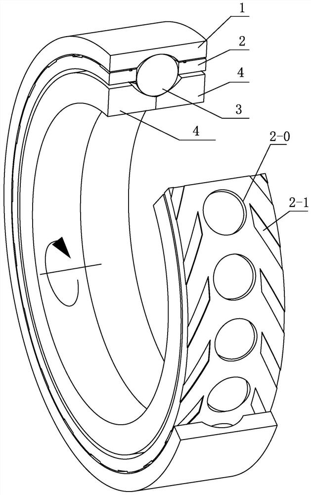
[0014] see figure 1 As shown, a double-half inner ring angular contact ball bearing with spiral grooves on the outer surface of the cage includes an outer ring 1, a cage 2, rolling elements 3 and an inner ring 4; the inner ring 4 is a double-half inner ring, and the inner ring A cage 2 is arranged between 4 and the outer ring 1, and the rolling element 3 is arranged in the cage pocket 2-0 and is in rolling contact with the inner ring 4 and the outer ring 1 respectively;

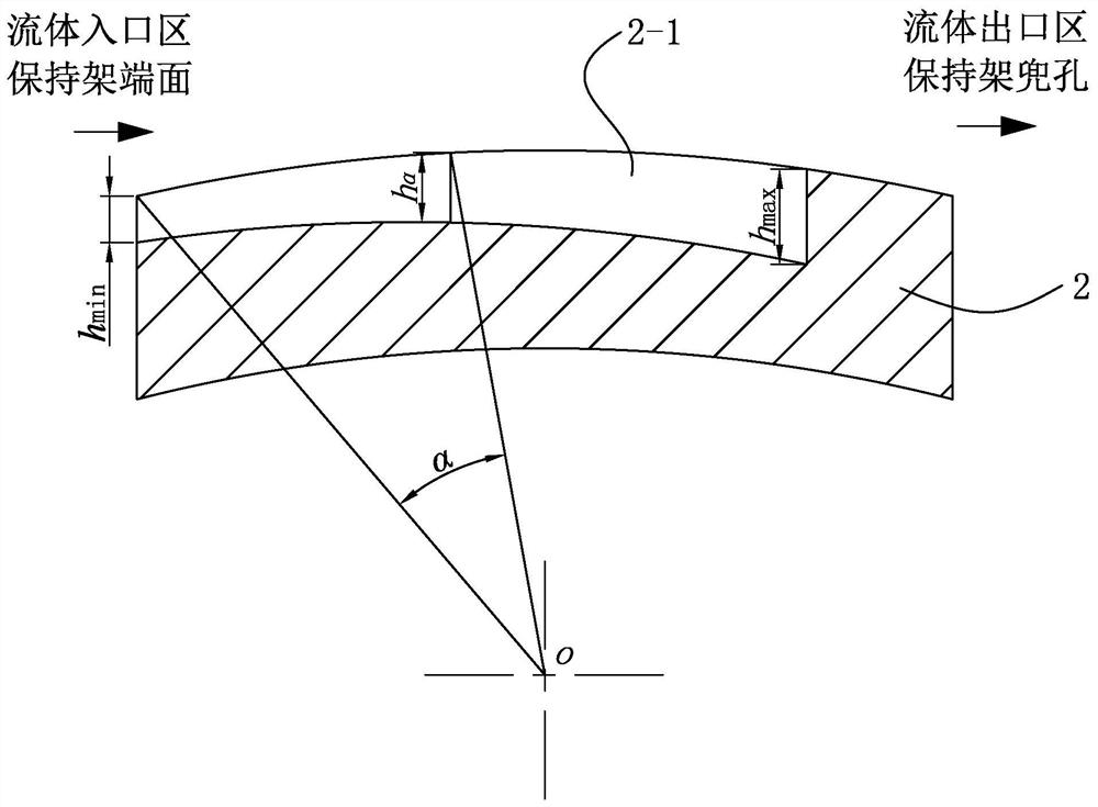
[0015] The outer surface of the cage 2 is provided with two groups of grooves 2-1, the two groups of grooves 2-1 are arranged on both sides of the cage pocket 2-0, and each group of grooves contains a plurality of grooves 2-1 , each groove 2-1 extends from the end face of the cage to the cage pocket 2-0, and the plurality of grooves 2-1 are spirally arranged in the circumferential direction, and the two groups of grooves 2-1 The direction of rotation is opposite.

[0016] Each groove 2-1 extends from the en...


PUM


Abstract

The invention discloses a double-half-inner-ring angular contact ball bearing with spiral grooves in the outer surface of a retainer. The bearing comprises an outer ring, the retainer, rolling bodiesand an inner ring. The inner ring is a double-half inner ring; the retainer is arranged between the inner ring and the outer ring; and the rolling bodies are arranged in pockets of the retainer and are in rolling contact with the inner ring and the outer ring respectively. The outer surface of the retainer is provided with two groups of grooves; the two groups of grooves are arranged at two sidesof the pockets of the retainer; each group of the grooves comprises multiple grooves; each groove extends from the end surface of the retainer to the pockets of the retainer; the multiple grooves arespirally arranged along the circumferential direction; and the rotating directions of the two groups of grooves are opposite. According to the double-half-inner-ring angular contact ball bearing withthe spiral grooves in the outer surface of the retainer, based on the dynamic pressure effect and the pumping function of the spiral groove microstructure, the micro-dynamic pressure effect is formedthrough the spiral groove structure between the retainer and a guide ferrule, and fluid is pumped into the contact surface, so that the multiple positive effects of increasing the thickness of a lubricating film on the contact surface, improving the bearing capacity, stabilizing the movement of the retainer and enhancing heat dissipation are achieved, and support is provided for the improvement ofaero-engine performance.

Description

technical field [0001] The invention relates to a novel angular contact ball bearing, in particular to a double-half inner ring angular contact ball bearing with spiral grooves on the outer surface of the cage. Background technique [0002] The main shaft of the aero-engine has the characteristics of large diameter and high speed, which makes the double-half inner ring angular contact ball bearing of the main shaft face the challenges of extreme working conditions such as high temperature and high load. At high speeds, when external guidance is used, the cage will expand due to centrifugal and thermal effects, resulting in a reduction in the guide gap and an increase in the instability of the cage, which will cause frequent contact between the cage and the guide surface and further increase in frictional heat. Increase. This coupling effect of high temperature and high speed reduces the bearing capacity of the oil film between the cage and the guide surface, which easily ca...

Claims


Application Information

Patent Timeline
Patent Type & Authority Applications(China)
IPC IPC(8): F16C19/16F16C33/66F16C33/38
CPCF16C19/163F16C33/38F16C33/66F16C33/6659F16C33/6681
Inventor 徐榕壑王黎钦赵小力古乐郑德志张传伟吴继强
Owner HARBIN INST OF TECH
Why Eureka
Try Eureka