Electric lifting type installation assisting device for current transformer of high-voltage switch cabinet

A technology for current transformers and high-voltage switchgears, which is applied in the field of electric lifting installation auxiliary devices for current transformers in high-voltage switchgears. Requirements, current transformers hurt workers, etc., to improve work efficiency and construction quality, improve power supply reliability, and reduce operating risks

Pending Publication Date: 2021-01-29
STATE GRID SHANDONG ELECTRIC POWER +1
View PDF8 Cites 2 Cited by
  • Summary
  • Abstract
  • Description
  • Claims
  • Application Information

AI Technical Summary

Problems solved by technology

[0002] With the increasing load demand of power supply users, the transformation ratio capacity of the existing current transformers in the 10kV-35kV high-voltage switchgear in the substation has not met the requirements, so most of the current transformers need to be replaced
Due to the narrow working space of the cable room at the back door of the switchgear and the middle and lower part of the rear of the switchgear is blocked by a partition (current transformer installation base), the operator cannot install the current transformer in a suitable position only by manpower
At present, operators often disassemble the partit

Method used


Image

  • Electric lifting type installation assisting device for current transformer of high-voltage switch cabinet
  • Electric lifting type installation assisting device for current transformer of high-voltage switch cabinet
  • Electric lifting type installation assisting device for current transformer of high-voltage switch cabinet

Examples


Embodiment Construction

[0023] In order to enable those skilled in the art to better understand the technical solutions in the present application, the technical solutions in the embodiments of the present application will be clearly and completely described below in conjunction with the drawings in the embodiments of the present application. Obviously, the described The embodiments are only some of the embodiments of the present application, but not all of them. Based on the embodiments in this application, all other embodiments obtained by persons of ordinary skill in the art without creative efforts shall fall within the scope of protection of this application.

[0024] Key terms appearing in this application are explained below.

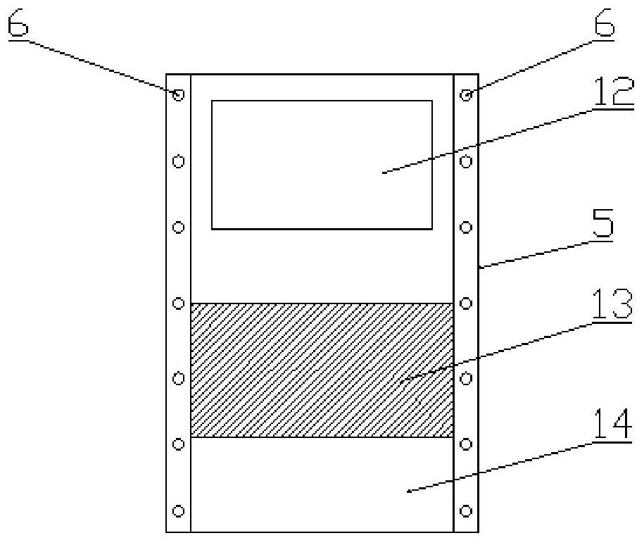
[0025] The electric lifting installation auxiliary device for high-voltage switchgear current transformer provided by this application includes a horizontal tube 1, an electric lifting device 2 and a current transformer hook assembly 3. The horizontal tube 1 adopts a ho...


PUM

PropertyMeasurementUnit
Lengthaaaaaaaaaa

Abstract

The invention provides an electric lifting type installation assisting device for a current transformer of a high-voltage switch cabinet, and relates to the technical field of current transformer installation. The electric lifting type installation assisting device comprises a transverse pipe, an electric lifting device and a current transformer hook assembly, hooks are arranged at the two ends ofthe transverse pipe respectively, and hanging holes matched with the hooks are formed in the switch cabinet. The current transformer hook assembly comprises a cross beam, a hanging ring is arranged on the upper portion of the cross beam, a lifting hook is arranged on the lower portion of the cross beam, the upper end of the electric lifting device is connected with the cross pipe through a firstconnecting piece, the lower end of the electric lifting device is connected with the hanging ring through a second connecting piece, and the lifting hook is connected with the current transformer. Theinstallation assisting device is simple in structure, low in cost, easy to install and capable of effectively improving the working efficiency and the construction quality, guaranteeing the operationsafety of construction personnel and guaranteeing that the replacement work of the current transformer is completed as expected when the current transformer of the 10kV-35kV high-voltage switch cabinet is replaced and installed.

Description

technical field [0001] The application relates to the technical field of current transformer installation, in particular to an electric lifting installation auxiliary device for a current transformer of a high-voltage switch cabinet. Background technique [0002] With the increasing load demand of power supply users, the transformation ratio capacity of the existing current transformers in the 10kV-35kV high-voltage switchgear in the substation has not met the requirements, so most of the current transformers need to be replaced. Due to the narrow working space of the cable room at the back door of the switchgear and the middle and lower part of the rear of the switchgear is blocked by a partition (current transformer installation base), the operator cannot install the current transformer in a suitable position only by manpower. At present, operators often disassemble the partition (current transformer installation base) as a whole, install the three current transformers on ...

Claims


Application Information

Patent Timeline
IPC IPC(8): H02B3/00B66C1/10B66C1/34B66C11/02
CPCH02B3/00B66C1/10B66C1/34B66C11/02
Inventor 亓延峰刘松赵信华王东华李波韩涛赵勇张建民葛华李鹏侯国强董子郁李春彦亓立红李娜高森亓晓娟
Owner STATE GRID SHANDONG ELECTRIC POWER
Why Eureka
Try Eureka