Multi-channel optical switching device

An optical switching and multi-channel technology, applied in the field of optical signal switching, can solve the problems of complex structure, inconvenient maintenance, and high cost of multi-channel optical switching devices, and achieve the effects of easy troubleshooting, reduced optical paths, and reduced insertion damage

Pending Publication Date: 2021-02-02
NO 34 RES INST OF CHINA ELECTRONICS TECH GRP
View PDF0 Cites 1 Cited by
  • Summary
  • Abstract
  • Description
  • Claims
  • Application Information

AI Technical Summary

Problems solved by technology

[0003] The present invention aims to solve the problems of complex structure, high cost and inconvenient maintenance in the multi-channel optical switching device, and provides a multi-channel optical switching device

Method used


Image

  • Multi-channel optical switching device
  • Multi-channel optical switching device

Examples


Embodiment Construction

[0018] In order to make the object, technical solution and advantages of the present invention clearer, the present invention will be further described in detail below in combination with specific examples and with reference to the accompanying drawings. It should be noted that the directional terms mentioned in the examples, such as "upper", "lower", "middle", "left", "right", "front", "rear", etc., are only referring to the directions of the drawings. Therefore, the directions used are only for illustration and are not intended to limit the protection scope of the present invention.

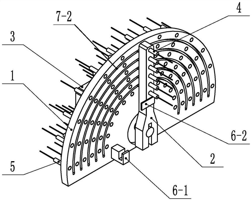
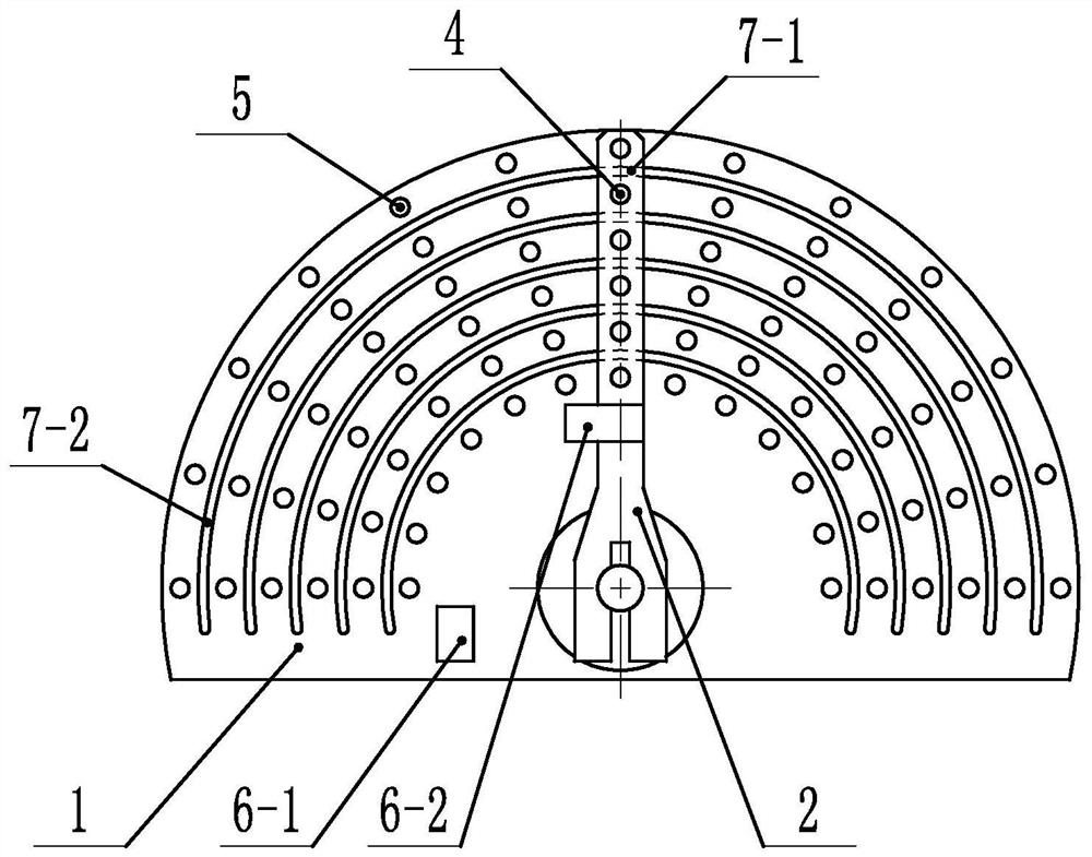
[0019] see figure 1 and 2 , a multi-channel optical switching device, consisting of a housing, an input collimator 4, an output collimator 5, a mirror base plate 1, a swing arm needle 2, a micro motor 3, a position sensor and a control circuit board. .

[0020] The mirror base plate 1 is similar to the dial of a clock, and the swing arm needle 2 is similar to the hands of a clock. Both the ...


PUM


Abstract

The invention discloses a multi-channel optical switching device which comprises an input collimator, an output collimator, a lens seat disc, a swing arm needle, a micro motor and a control circuit board. The micro motor is electrically connected with the control circuit board; when light path switching is carried out, the micro motor is started under the control of the control circuit board, andthe swing arm needle is driven by the micro motor to rotate clockwise or anticlockwise by taking the central hole of the microscope base plate as an axis; and the input collimators on the group of input holes on the lens seat disc are conducted with the output collimators on one group of output holes on the lens seat disc. According to the multi-channel optical switching device, switching of optical paths of the multi-channel optical switching device can be achieved in a mechanical control mode, the multi-channel optical switching device has the advantages of being low in insertion loss, largein channel number, high in isolation degree, free of light in wavelength and polarization and the like, the size and complexity of the multi-channel optical switching device can be reduced, the production cost is reduced, and troubleshooting is easier.

Description

technical field [0001] The invention relates to the technical field of optical signal switching, in particular to a multi-channel optical switching device. Background technique [0002] As a key component of all-optical networks, multi-channel optical switching devices are widely used in the fields of all-optical routing, multi-channel monitoring, device testing, optical network cross-links, and self-healing protection. On-off and switching control of each optical path. When the existing optical switching device switches multiple optical paths, for each optical path, its common practice is to set 1×N light beams between the input single-core collimator and the output single-core collimator of the optical path. switch, and control N 1×N optical switches through a single-chip microcomputer control circuit, and then achieve the purpose of controlling the on-off and switching of multiple optical paths. However, with the development of optical communication transmission network...

Claims


Application Information

Patent Timeline
Patent Type & Authority Applications(China)
IPC IPC(8): G02B6/35
CPCG02B6/354G02B6/3548G02B6/3564
Inventor 钟昌锦刘斌付益鲁正阳泽恒曾笑波汤科童章伟雷静
Owner NO 34 RES INST OF CHINA ELECTRONICS TECH GRP
Why Eureka
Try Eureka