
Efficient stone crushing and screening device for constructional engineering

A technology of construction engineering and screening device, which is applied in the direction of grain processing, etc., can solve the problems of uneven size and low crushing efficiency, and achieve the effect of uniform size, good crushing effect, and quality assurance

Inactive Publication Date: 2021-02-05
郑州正大建筑技术有限公司
View PDF8 Cites 2 Cited by
  • Summary
  • Abstract
  • Description
  • Claims
  • Application Information

AI Technical Summary

Problems solved by technology

[0005] The object of the present invention is to provide a high-efficiency gravel screening device for construction engineering with high crushing efficiency and uniform size for the above-mentioned problems of low crushing efficiency and uneven size

Method used


Image

  • Efficient stone crushing and screening device for constructional engineering
  • Efficient stone crushing and screening device for constructional engineering

Examples


Embodiment 1

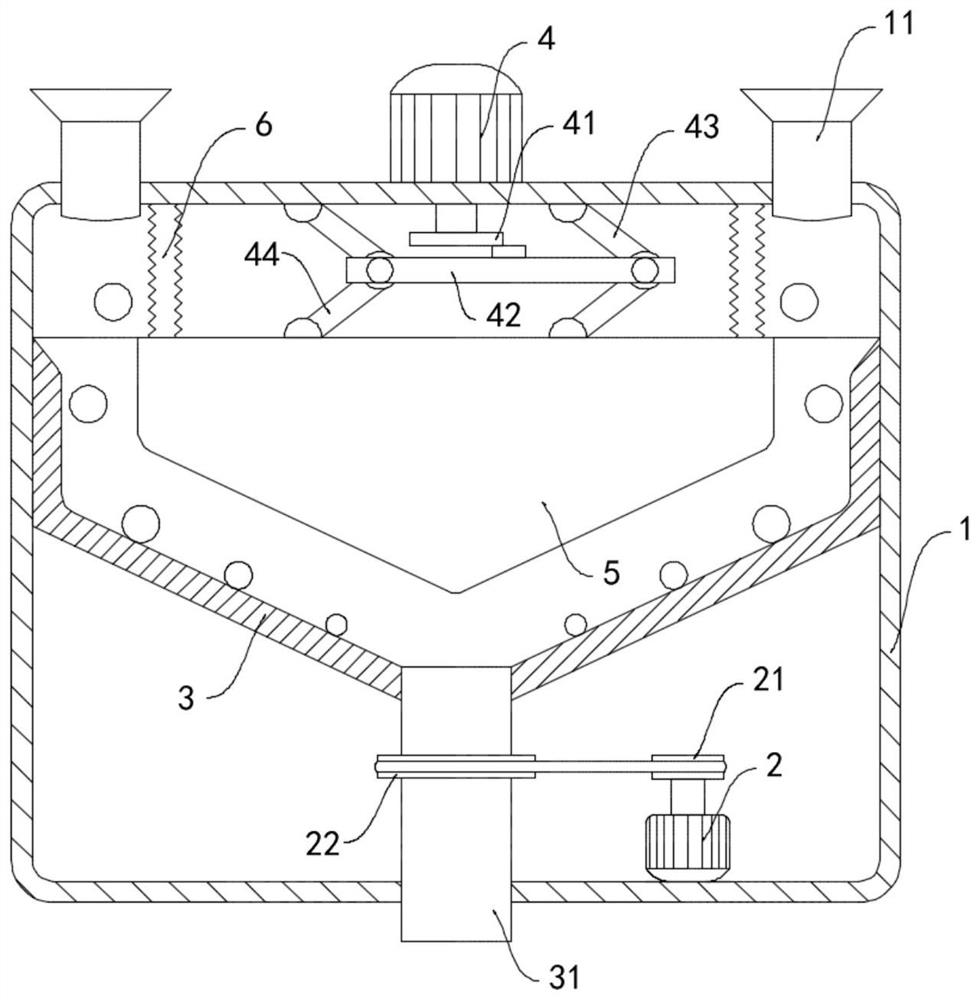
[0021] like figure 1 As shown, a high-efficiency gravel screening device for construction engineering includes a device housing 1, the upper end of the device housing 1 is connected with a feed hopper 11, the inner bottom surface of the device housing 1 is equipped with a first motor 2, and the device housing The inner wall of the body 1 is rotatably connected with a gravel cylinder 3, the center of the bottom of the gravel cylinder 3 is sunken downwards and is fixedly connected with a discharge pipe 31, and the lower end of the discharge pipe 31 runs through the bottom surface of the device housing 1 And connected with the device housing 1 in rotation, the first motor 2 is connected with the transmission of the gravel cylinder 3, the output shaft of the first motor 2 is fixedly sleeved with the first pulley 21, and the outer discharge pipe 31 is fixedly sleeved with the second belt pulley. The belt pulley 22, the first belt pulley 21 and the second belt pulley 22 are connecte...

Embodiment 2

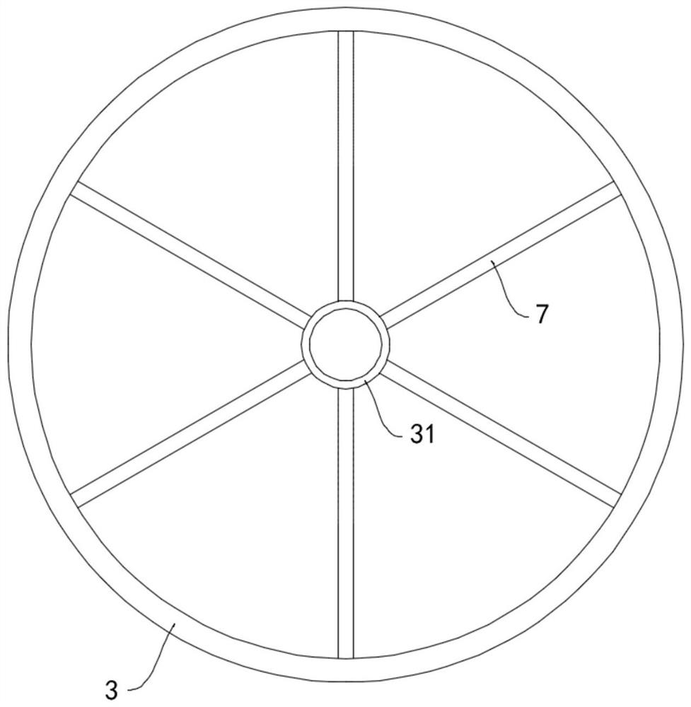
[0027] like figure 2 As shown, the difference between this embodiment and Embodiment 1 is that the inner bottom surface of the gravel cylinder 3 is fixedly connected with a plurality of protruding ribs 7 extending from the center to the surroundings, and the plurality of protruding ribs 7 are in an annular array. arranged.

[0028] In this embodiment, when the stone rolls on the inner bottom surface of the crushing cylinder 3, the raised ribs 7 rotate with the crushing cylinder 3 to further impact and crush the stone, and at the same time, the stone is easy to bounce under the impact of the raised ribs 7 After falling, its shattering effect has been improved.


PUM


Abstract

The invention belongs to the field of civil engineering mechanical equipment, and particularly relates to an efficient stone crushing and screening device for constructional engineering. The efficientstone crushing and screening device for constructional engineering comprises a device shell body, the upper end of the device shell body is communicated with a feeding hopper, a first motor is installed on the inner bottom face of the device shell body, a stone crushing barrel body is rotatably connected to the inner side wall of the device shell body, the center of the bottom of the stone crushing barrel body is sunken downwards and is fixedly communicated with a discharging pipe, the lower end of the discharging pipe penetrates through the bottom face of the device shell body and is rotationally connected with the device shell body, the first motor is in transmission connection with the stone crushing barrel body, a second motor is installed at the upper end of the device shell body, and vibrating blocks are arranged in the stone crushing barrel body. According to the efficient stone crushing and screening device for constructional engineering, crushing can be carried out through collision among all stones and repeated collision of the vibrating blocks, so that the crushing effect is good, and the efficiency is high; and small stones obtained after crushing is completed are screened out through the centrifugal force of rotation of the crushing barrel body, so that the sizes of the stones are uniform, and the quality of civil engineering construction is guaranteed.

Description

technical field [0001] The invention belongs to the field of civil construction machinery and equipment, and in particular relates to a high-efficiency gravel screening device for construction engineering. Background technique [0002] With the expansion of the scale of civil construction engineering, construction tools, equipment, and machinery are also developing towards multi-variety, automation, and large-scale development. Therefore, it is very important to efficiently crush stone raw materials during the construction of civil engineering projects. [0003] In the prior art, impact or centrifugal crushers are often used to crush stone raw materials. However, most of these crushing methods have simple structures, limited crushing effects, low work efficiency, and uneven sizes of crushed stones, which affect civil engineering. Progress of building construction. [0004] To this end, we propose a high-efficiency gravel screening device for construction to solve the above...

Claims


Application Information

Patent Timeline
Patent Type & Authority Applications(China)
IPC IPC(8): B02C1/14B02C19/00B02C23/16
CPCB02C1/14B02C19/0012B02C23/16B02C2023/165
Inventor 王利郭保林
Owner 郑州正大建筑技术有限公司
Learn More