Auxiliary support and moving device for machine tool processing super long workpiece

A technology of auxiliary support and moving device, applied in metal processing machinery parts, metal processing equipment, manufacturing tools, etc., can solve problems such as instability, impact on construction period, large outsourcing costs, etc., to reduce the impact of height errors, shorten the The effect of processing time and reducing processing cost

Active Publication Date: 2022-02-01
上海宝冶工程技术有限公司 +1
View PDF8 Cites 0 Cited by
  • Summary
  • Abstract
  • Description
  • Claims
  • Application Information

AI Technical Summary

Problems solved by technology

[0002] When the machine tool is working, the length of the workpiece to be processed must match the stroke of the machine tool. If the workpiece exceeds the stroke of the machine tool too much, the workpiece will be deformed and unstable due to the lack of support at the tail end of the workpiece, and the machining accuracy of the workpiece cannot be guaranteed.
In the prior art, there is a method of supporting the workpiece with a bracket with casters. The method is: the bracket with casters supports the tail end of the workpiece. When the machine tool drives the workpiece to move, the bracket is driven by the workpiece to follow the movement. This method is difficult to ensure that the moving track of the bracket is consistent with the guide rail of the machine tool Parallel, the guide rail of the machine tool is subjected to transverse shear force and longitudinal shear force in the cross-sectional direction, which will damage the guide rail of the machine tool and affect the accuracy of the machine tool
Therefore, when the length of the workpiece exceeds the stroke of the machine tool, it is necessary to find outsourcing processing, but it is difficult to find outsourcing for large-scale machine tools, which will easily affect the construction period, and the cost of outsourcing is huge

Method used


Image

  • Auxiliary support and moving device for machine tool processing super long workpiece
  • Auxiliary support and moving device for machine tool processing super long workpiece
  • Auxiliary support and moving device for machine tool processing super long workpiece

Examples


Embodiment Construction

[0036] In the following description, numerous specific details are given in order to provide a more thorough understanding of the present invention. It will be apparent, however, to one skilled in the art that the present invention may be practiced without one or more of these details. In other examples, some technical features known in the art are not described in order to avoid confusion with the present invention.

[0037] In order to thoroughly understand the present invention, detailed steps and detailed structures will be provided in the following description, so as to illustrate the technical solution of the present invention. Preferred embodiments of the present invention are described in detail below, however, the present invention may have other embodiments besides these detailed descriptions.

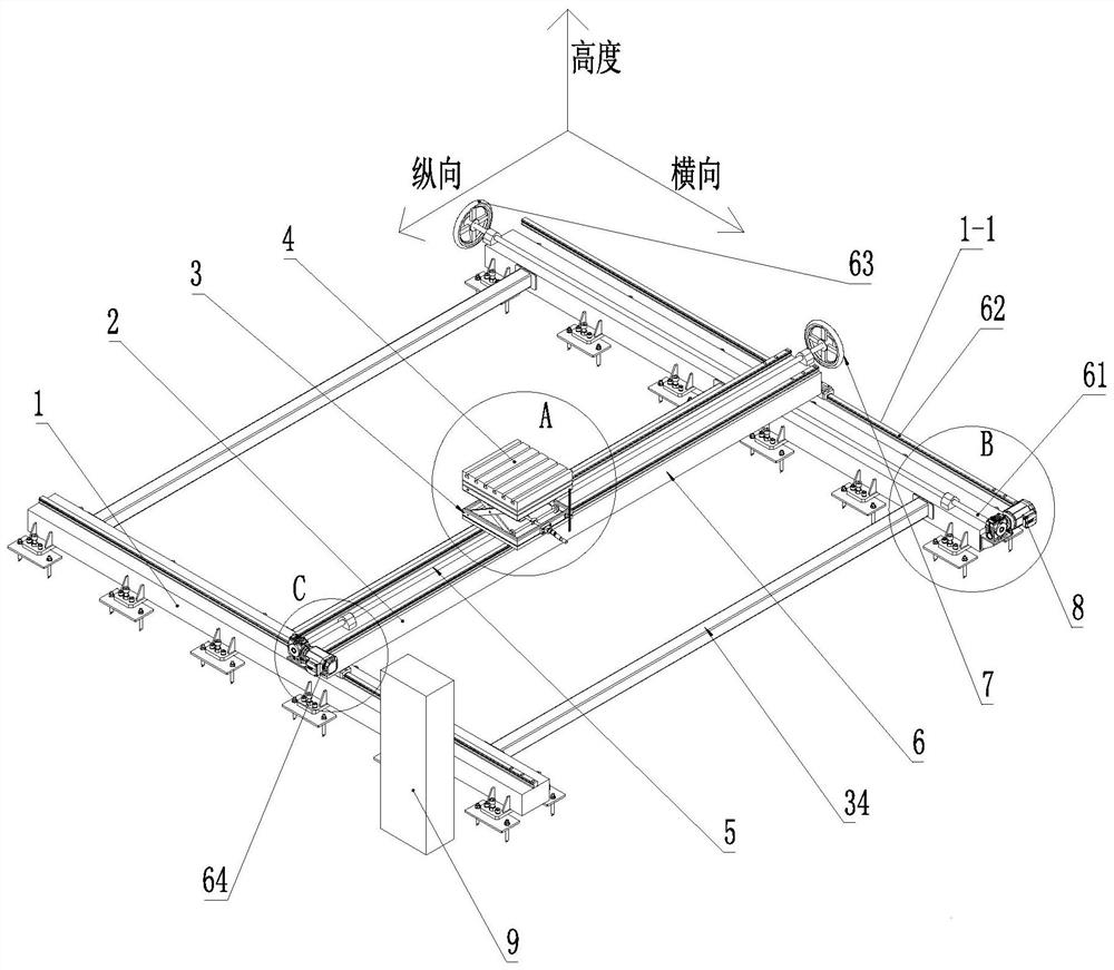
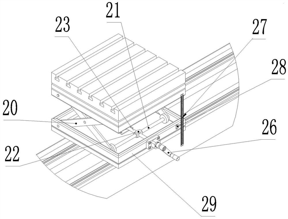
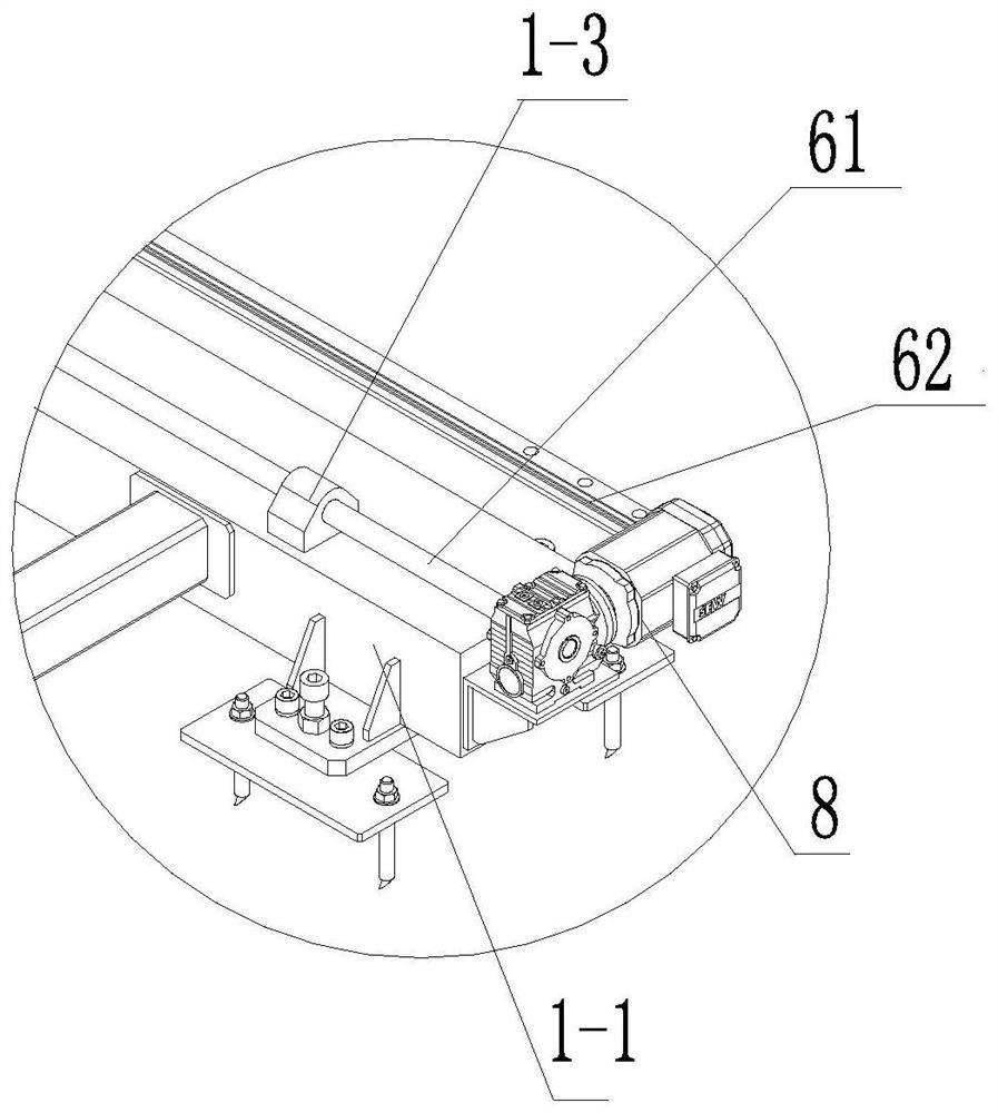
[0038] The present invention provides an auxiliary supporting and moving device for machine tool processing super-long workpieces. The auxiliary supporting and moving device...


PUM


Abstract

The invention provides an auxiliary supporting and moving device for machine tool processing super long workpieces, comprising: two beams, a first transmission screw rod is arranged on the first beam, one end of the first transmission screw rod is fixed with a handwheel, and the other end It is connected with the deceleration motor; the longitudinal beam is slidably installed between two beams, and the second transmission screw rod is arranged on the longitudinal beam. One end of the second transmission screw rod is fixed with a hand wheel, and the other end is connected with the deceleration motor; the height lifting mechanism , slidingly installed on the second transmission screw, the lifting drive device is provided with two lifting screws and connecting rods that are crossed and connected in rotation, one end of the lifting screw is fixedly connected with the crank, the other end is connected with the geared motor, and the connecting rod The end is fixedly connected with the scissor-type connecting rod, and a horizontally rotatable table is arranged on the top of the height-lifting mechanism. The invention can use a machine tool with a short stroke to process super-long workpieces without looking for outsourced processing, shortens the processing period, reduces processing costs, and has significant economic benefits.

Description

technical field [0001] The invention relates to mechanical processing, in particular to an auxiliary support and moving device for processing super-long workpieces by machine tools. Background technique [0002] When the machine tool is working, the length of the workpiece to be processed must match the stroke of the machine tool. If the workpiece exceeds the stroke of the machine tool too much, the workpiece will be deformed and unstable due to the lack of support at the tail end of the workpiece, and the machining accuracy of the workpiece cannot be guaranteed. In the prior art, there is a method of supporting the workpiece with a bracket with casters. The method is: the bracket with casters supports the tail end of the workpiece. When the machine tool drives the workpiece to move, the bracket is driven by the workpiece to follow the movement. This method is difficult to ensure that the moving track of the bracket is consistent with the guide rail of the machine tool Paral...

Claims


Application Information

Patent Timeline
Patent Type & Authority Patents(China)
IPC IPC(8): B23Q1/01B23Q1/25
CPCB23Q1/017B23Q1/25
Inventor 程绍硕杨天君廖福迪裴乐文郭林恩石佳文秦雄
Owner 上海宝冶工程技术有限公司
Why Eureka
Try Eureka