Eureka AIR delivers breakthrough ideas for toughest innovation challenges, trusted by R&D personnel around the world.

Integral electroforming method and dedicated die of three-dimensional sculpture

A three-dimensional, electroforming technology, applied in electroforming and electrolysis processes, etc., can solve the problems of time-consuming, labor-intensive, easy to produce deformation, and long construction period.

Inactive Publication Date: 2010-11-10
DALIAN JIAHUA ART DEV
View PDF5 Cites 0 Cited by
  • Summary
  • Abstract
  • Description
  • Claims
  • Application Information

AI Technical Summary

Problems solved by technology

[0003] 1. Metal smelting not only requires heat energy, but also requires enhanced ventilation equipment to discharge a large amount of waste gas (flue gas from coke ovens, gas furnaces or oil furnaces, gases produced by gasification of some metals and fluxes) generated during the heating process to the air , a large amount of energy is wasted;
[0004] 2. The process of manufacturing molds is complicated, and some molds have to be dewaxed by heating and strengthened by high-temperature roasting, and the operating environment is harsh, which is not conducive to environmental protection;
[0005] 3. After casting, it is necessary to repair and finish the casting. It needs to be equipped with welding machine, welding torch, cutting machine, polishing machine, polishing machine and decorative drilling tools, etc., which is time-consuming, laborious and high processing cost;
[0009] 1. There are many processes such as slicing, research and matching, and assembly welding, which are not only time-consuming and labor-intensive, but also have a long construction period and are prone to deformation;
[0010] 2. The ornamentation at the welding joint and weld seam is damaged and must be manually repaired, and the similarity with the original mold is difficult to reach 100%.

Method used


Image

  • Integral electroforming method and dedicated die of three-dimensional sculpture
  • Integral electroforming method and dedicated die of three-dimensional sculpture

Examples


Embodiment Construction

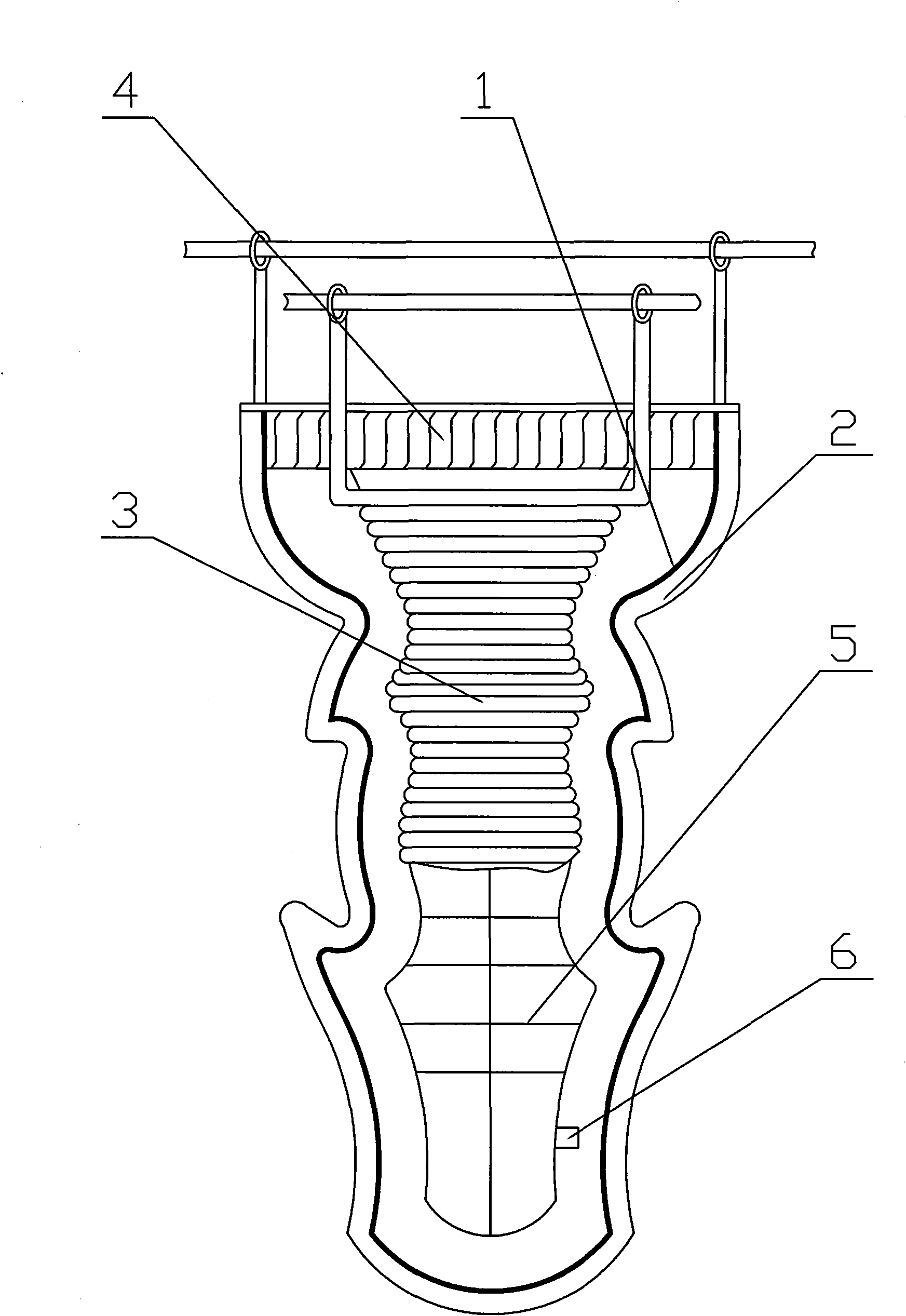
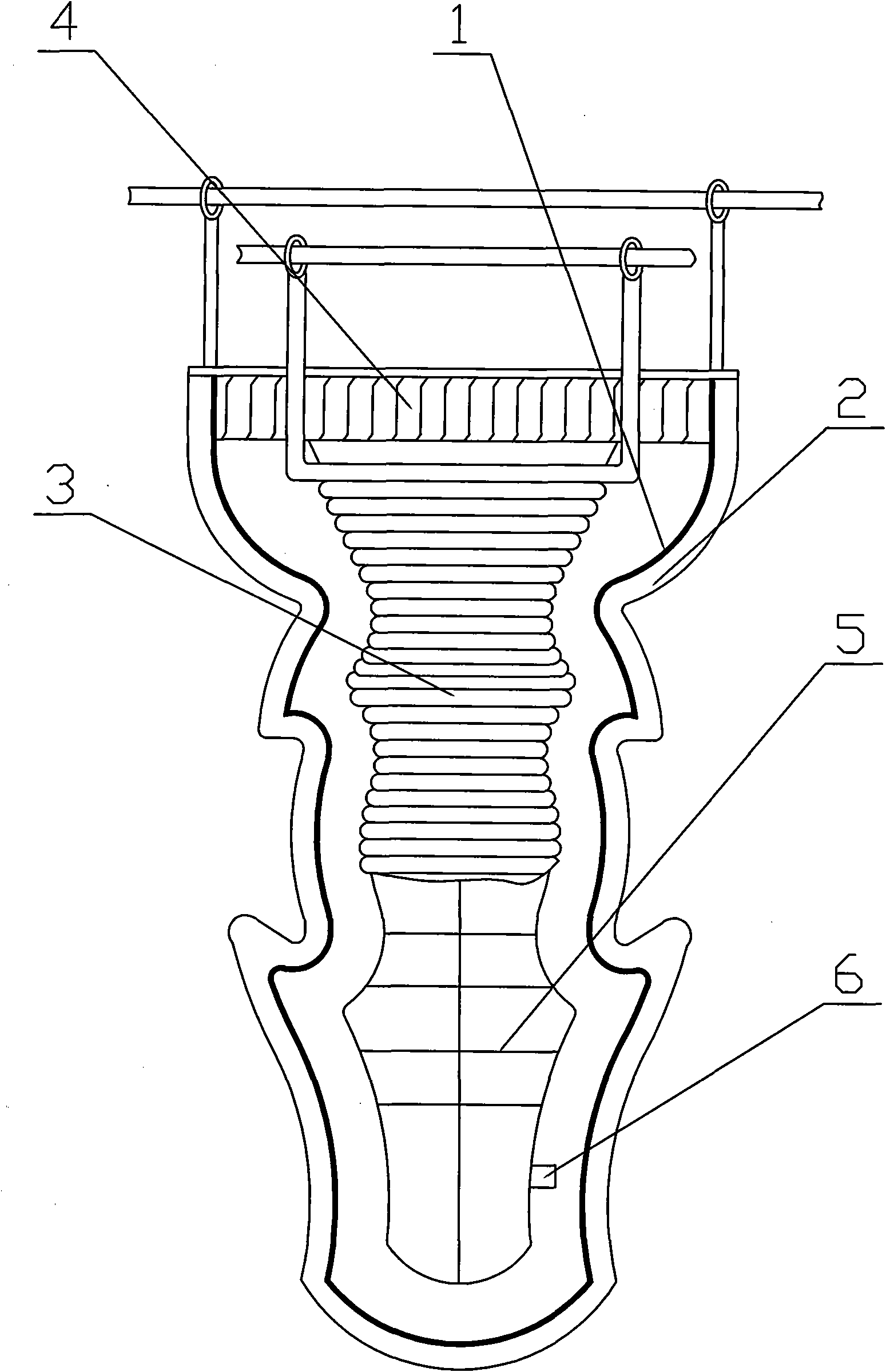
[0023] The specific implementation manner of the present invention will be described below with reference to the accompanying drawings. The special mold of the present invention such as figure 1 As shown: there is a three-dimensional hollow female mold 2 made of insulating materials such as silica gel or gypsum, the upper part is open, and the inner wall is coated with a conductive layer 1. A conductive electrode 4 connected to the conductive layer 1 is provided at the opening of the female mold 2; At the same time, a three-dimensional conformal anode 3 that can be placed in the inner cavity of the female mold 2 is provided. The three-dimensional conformal anode 3 is a three-dimensional shape, and the distance between its outer surface and the conductive layer 1 is 1 to 7 cm, that is, as long as the three-dimensional conformal anode 3 The shortest distance between each point on the outer surface and the conductive layer 1 can be in the range of 1-7 cm, which can be the same or...


PUM


Abstract

The invention discloses an integral electroforming method of three-dimensional sculpture, which can reserve the advantages of separated electroforming and time and labour saving for processing and has the 100% similarity with a master mould. The integral electroforming method comprises: a three-dimensional hollow female die (2) of which the upper part is provided with an opening and the inner wall is coated with a conducting layer (1) is installed in a electrolytic cell; the inner cavity of the female die (2) is provided with a three-dimensional natural shape anode (3) of which the external surface is corrugated; the space between the external surface of the natural shape anode (3) and the conducting layer (1) is 1-7 cm, and the area ratio of the external surface of the natural shape anode (3) and the conducting layer (1) is 1.5-2:1; electrolyte is filled into the electrolytic cell; a female die conducting electrode (4) and the three-dimensional natural shape anode (3) are connected with a power supply; a metal casting layer with set thickness is accumulated on the conducting layer (1) by electroforming; and the female die (2) coated with the metal casting layer is taken out and is removed.

Description

Technical field: [0001] The invention relates to a three-dimensional sculpture electroforming method, in particular to a three-dimensional sculpture integral electroforming method and a special mold which can retain the advantages of separate electroforming, save time and effort in processing, and have a similarity with the original mold of 100%. Background technique: [0002] In the past, the "fire method" casting process was used for metal sculpture products, whether it was flat relief or three-dimensional round sculpture, that is, the metal material was melted into a liquid, and then the molten metal was poured into a prefabricated high-refractoriness, high-strength casting mold. After the molten metal is cooled and formed, the mold is removed, repaired and finished. The main disadvantages of the "fire method" casting process are as follows: [0003] 1. Metal smelting not only requires heat energy, but also requires enhanced ventilation equipment to discharge a large amo...

Claims


Application Information

Patent Timeline
IPC IPC(8): C25D1/02C25D1/10
Inventor 贺传忠扶粤凌贺业宏
Owner DALIAN JIAHUA ART DEV
Why Eureka
Eureka Blog
Learn More