
Multi-wire cutting machine for processing solar cell panels

A solar panel and multi-wire cutting machine technology, which is applied to stone processing equipment, work accessories, manufacturing tools, etc., can solve the problems of affecting cutting accuracy, cutting misalignment, and solar panels cannot be well limited and fixed. To achieve the effect of convenient taking and placing, and improving quality

Active Publication Date: 2021-02-05
湖南旭昱新能源科技有限公司
View PDF7 Cites 2 Cited by
  • Summary
  • Abstract
  • Description
  • Claims
  • Application Information

AI Technical Summary

Problems solved by technology

[0002] Compared with ordinary batteries and rechargeable batteries, solar cells are more energy-saving and environmentally friendly green products. The main material of most solar panels is silicon, and crystalline silicon materials (including polycrystalline silicon and monocrystalline silicon) are the most important photovoltaic materials. , when the solar panel is being processed, it needs to be sliced ​​first, and the silicon rod is cut into a square silicon wafer by using multi-wire cutting. However, when the existing multi-wire cutting machine is in operation, the solar panel cannot be cut on the workbench. The limit is fixed very well, which will easily cause displacement during cutting, which will affect the cutting accuracy, and the workbench can only drive the solar panel to move up and down for cutting. When the solar panel is placed on the workbench, due to the solar battery The specifications of the panels are different, so it is not sure that the solar panel is facing the cutting line, resulting in misalignment of the cutting

Method used


Image

  • Multi-wire cutting machine for processing solar cell panels
  • Multi-wire cutting machine for processing solar cell panels
  • Multi-wire cutting machine for processing solar cell panels

Examples


Embodiment Construction

[0030] The present invention will be further described below in conjunction with the accompanying drawings.

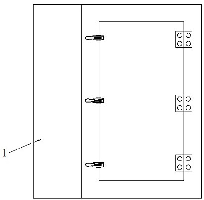
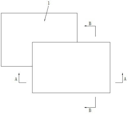
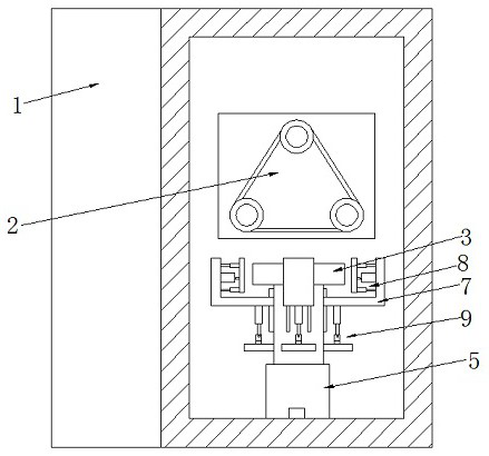
[0031] see as Figure 1-Figure 10 As shown, the technical solution adopted in this specific embodiment is: it includes a body body 1, a wire rack 2 and a workbench 3, a wire rack 2 is arranged in the body body 1, and a workbench 3 is arranged on the lower side of the wire rack 2; Including the No. 1 cylinder 4, the lifting seat 5, the fixed support block 6, the support frame 7, the side limit mechanism 8 and the adjustment support mechanism 9, the No. 1 cylinder 4 of the model TN20 is fixed on the rear inner wall of the body body 1 by screws , the push end of the No. 1 cylinder 4 is welded and fixed with a lifting seat 5, the lift seat 5 includes a support seat 5-1 and an adjustment seat 5-2, the support seat 5-1 is welded and fixed with the push end of the No. 1 cylinder 4, and the support seat The inner bottom surface of the 5-1 is fixed with the No. 2 cylinder 5-3 ...


PUM


Abstract

The invention discloses a multi-wire cutting machine for processing solar cell panels, and relates to the technical field of new energy processing equipment. The multi-wire cutting machine is characterized in that a first air cylinder is fixed to the inner wall of the rear side of a machine body, a lifting base is fixed to the pushing end of the first air cylinder, a workbench is fixed to the lifting base, fixed supporting blocks are fixed to the periphery of the lifting base, a supporting frame is arranged on the upper sides of the fixed supporting blocks and is of an L-shaped structure, thevertical end in the supporting frame is arranged on the outer side of the workbench, an adjusting supporting mechanism is arranged between the bottom of the supporting frame and the fixed supporting blocks, and a side limiting mechanism is arranged between the vertical end in the supporting frame and the workbench. According to the multi-wire cutting machine for processing the solar cell panels, the to-be-cut solar cell panels can be limited and clamped, so that the solar cell panels are in a stable state during cutting, besides, the solar cell panels can be driven to move to the positions under the cutting line according to different specifications of the solar cell panels, and the cutting quality is improved.

Description

technical field [0001] The invention relates to the technical field of new energy processing equipment, in particular to a multi-wire cutting machine for processing solar panels. Background technique [0002] Compared with ordinary batteries and rechargeable batteries, solar cells are more energy-saving and environmentally friendly green products. The main material of most solar panels is silicon, and crystalline silicon materials (including polycrystalline silicon and monocrystalline silicon) are the most important photovoltaic materials. , when the solar panel is being processed, it needs to be sliced ​​first, and the silicon rod is cut into a square silicon wafer by using multi-wire cutting. However, when the existing multi-wire cutting machine is in operation, the solar panel cannot be cut on the workbench. The limit is fixed very well, which will easily cause displacement during cutting, which will affect the cutting accuracy, and the workbench can only drive the solar ...

Claims


Application Information

Patent Timeline
IPC IPC(8): B28D5/04B28D7/04B28D7/00
CPCB28D5/045B28D5/0082B28D5/0064B28D5/0058
Inventor 姚群刘禹辰刘亮刘海曾劲刚
Owner 湖南旭昱新能源科技有限公司
Learn More