A drying device with three-dimensional floating function and its implementation method

A technology of drying equipment and functions, which is used in drying cargo handling, drying solid materials, lighting and heating equipment, etc., can solve the problems of inability to manually control all-round drying of materials, uncontrollable material running trajectories, poor drying effect, etc. The effect of running path length, improving drying efficiency, and prolonging drying time

Active Publication Date: 2021-12-14
深圳市春旺新材料股份有限公司
View PDF13 Cites 0 Cited by
  • Summary
  • Abstract
  • Description
  • Claims
  • Application Information

AI Technical Summary

Problems solved by technology

However, in the above-mentioned patents, a blower is used as the driving force for drying materials to float, resulting in an uncontrollable trajectory of the materials, and it is impossible to manually control the materials to achieve all-round drying, and there are materials attached to the inner wall of the equipment, which makes cleaning difficult, and the materials move in between in the drying box. , the moving path is short, the drying time is short, and the drying effect is poor

Method used


Image

  • A drying device with three-dimensional floating function and its implementation method
  • A drying device with three-dimensional floating function and its implementation method
  • A drying device with three-dimensional floating function and its implementation method

Examples


Embodiment 1

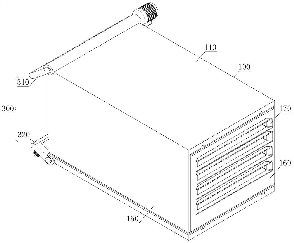
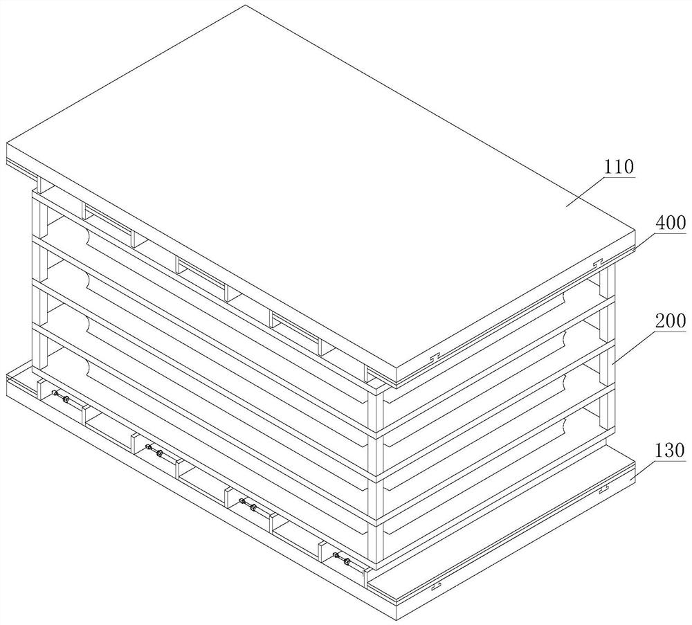
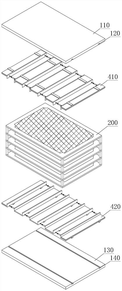
[0039] refer to Figure 1 to Figure 3, a drying equipment with a three-dimensional floating function, comprising a drying box 100, a drying core 200, a feed opening position control device 300 and a floating device 400, the left end of the drying box 100 is provided with a feed opening position control device 300, and the drying box Inside the 100 are installed a floating device 400 and a drying core 200 .

[0040] The drying box 100 includes a top plate 110, a top plate chute 120, a bottom plate 130, a bottom plate chute 140, a side plate 150, a rear end plate 160 and a discharge port 170, and two mutually parallel top plate chutes are provided on the lower bottom surface of the top plate 110. 120, the upper surface of the bottom plate 130 is provided with two parallel bottom plate chutes 140, the top plate 110 and the bottom plate 130 are fixedly connected by two parallel side plates 150, and the left end of the drying box 100 is an open feeding port , the right end is prov...

Embodiment approach

[0047] refer to Figure 10 , in order to better demonstrate the implementation process of the drying equipment with the three-dimensional floating function, this embodiment now proposes an implementation method of the drying equipment with the three-dimensional floating function, including the following steps:

[0048] S101: Forming a magnetic field, electrifying the magnetic plates 415, forming a magnetic field between two overlapping magnetic plates 415 in the vertical direction, and forming a gravity field between two adjacent magnetic plates 415 overlapping in the horizontal direction; 412 telescopic length, adjust the width of the magnetic field and gravity field in the horizontal direction

[0049] S102: initial speed, the driving motor 314 drives the fan 311 to rotate, sucks the material to be dried into the drying box 100, and at the same time gives the material to be dried an initial speed; the rotating shaft 330 can be driven to rotate by the rotating motor 340, and ...

Embodiment 2

[0052] refer to Figure 8 , a drying equipment with a three-dimensional floating function, comprising a drying box 100, a drying core 200, a feed opening position control device 300 and a floating device 400, the left end of the drying box 100 is provided with a feed opening position control device 300, and the drying box Inside the 100 are installed a floating device 400 and a drying core 200 .

[0053] The drying box 100 includes a top plate 110, a top plate chute 120, a bottom plate 130, a bottom plate chute 140, a side plate 150, a rear end plate 160 and a discharge port 170, and two mutually parallel top plate chutes are provided on the lower bottom surface of the top plate 110. 120, the upper surface of the bottom plate 130 is provided with two parallel bottom plate chutes 140, the top plate 110 and the bottom plate 130 are fixedly connected by two parallel side plates 150, and the left end of the drying box 100 is an open feeding port , the right end is provided with a...


PUM


Abstract

The invention discloses a drying equipment with a three-dimensional floating function and an implementation method thereof, belonging to the technical field of drying equipment, comprising a drying box, a drying core, a position control device for a feed inlet and a floating device. The left end of the drying box is provided with a The position control device of the feed port, and the inside of the drying box is equipped with a floating device and a drying core. The electromagnetic field is formed after the magnetic plate is energized, and the electromagnetic field cooperates with the gravity field to provide upward floating force and downward floating force for the iron object to be dried. The material entering the drying box runs in a wave-like trajectory and is suspended in the air. Drying in the dry state can not only achieve unobstructed all-round drying, but also avoid material adhesion; it also prolongs the length of the running path of the material in the drying box, prolongs the drying time, and improves the drying efficiency.

Description

technical field [0001] The invention relates to the technical field of drying equipment, in particular to a drying equipment with a three-dimensional floating function and an implementation method thereof. Background technique [0002] Drying equipment is also called dryer and dryer. The equipment used for drying operation, the moisture in the material (generally refers to water or other volatile liquid components) is vaporized and escaped by heating to obtain a solid material with a specified moisture content. The purpose of drying is to meet the needs of material use or further processing. For example, the drying of wood before making wooden molds and wooden utensils can prevent product deformation, and the drying of ceramic blanks before calcination can prevent cracking of finished products. In addition, the dried materials are also convenient for transportation and storage, such as drying the harvested grains below a certain moisture content to prevent mildew. Since n...

Claims


Application Information

Patent Timeline
Patent Type & Authority Patents(China)
IPC IPC(8): F26B19/00F26B23/06F26B25/00F26B25/02H02N15/00
CPCF26B19/00F26B23/06F26B25/001F26B25/02H02N15/00
Inventor 陈开琴
Owner 深圳市春旺新材料股份有限公司
Why Eureka
Try Eureka