Slitting equipment for battery steel shell machining

A battery steel shell and equipment technology, applied in the field of cutting equipment for battery steel shell processing, can solve the problems of troublesome cutting, inability to guarantee the stability of the steel shell during cutting, inconvenient use, etc., and achieve convenient use and unified processing and utilization Effect

Pending Publication Date: 2021-02-09
无锡市力达金属制品有限公司
View PDF6 Cites 0 Cited by
  • Summary
  • Abstract
  • Description
  • Claims
  • Application Information

AI Technical Summary

Problems solved by technology

[0004] The purpose of the present invention is to solve the problem that the existing cutting equipment for battery steel shells is inconvenient to use, cannot guarantee the stability of the steel shell during cutting, and is troublesome to unload, and can not perform well on the debris generated during cutting. Due to the shortcomings of recycling, a cutting equipment for battery steel case processing is proposed

Method used


Image

  • Slitting equipment for battery steel shell machining
  • Slitting equipment for battery steel shell machining
  • Slitting equipment for battery steel shell machining

Examples


Embodiment 1

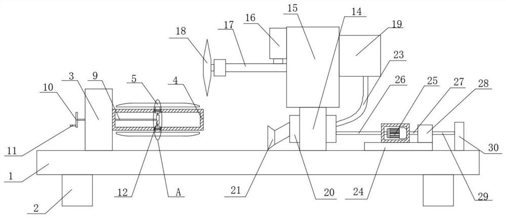
[0026] refer to Figure 1-5 , a cutting device for battery steel case processing, comprising a base plate 1, two brackets 2 are symmetrically fixedly mounted on the bottom of the base plate 1, a mounting plate 3 is fixedly mounted on the top of the base plate 1, and a mounting plate 3 is fixedly mounted on one side of the mounting plate 3. Tube 4, two stabilizing plates 5 are installed symmetrically slidingly on the placement tube 4, a rotating rod 9 is installed on the placement tube 4, and a circular plate 10 is fixedly installed on one end of the rotating rod 9, and a handle is fixedly installed on one side of the circular plate 10 11. The rotating rod 9 cooperates with the two stabilizing plates 5, and the top of the bottom plate 1 is symmetrically fixed with two support plates 14, and the top of the two support plates 14 is fixedly installed with the same top plate 15, and one side of the top plate 15 is fixedly installed There is an electric push rod 16, a fixed plate 17...

Embodiment 2

[0035] refer to Figure 1-5, a kind of cutting equipment for battery steel shell processing, comprising a base plate 1, the bottom of the base plate 1 is symmetrically fixed with two brackets 2 by welding, the top of the base plate 1 is fixedly installed with a mounting plate 3 by welding, and one side of the mounting plate 3 A placement tube 4 is fixedly installed by welding, and two stabilizing plates 5 are installed on the placement tube 4 for symmetrical sliding, and a rotating rod 9 is installed on the placement tube 4, and a circular plate 10 is fixedly installed on one end of the rotating rod 9 by welding. One side of 10 is fixedly equipped with a handle 11 by welding, the rotating rod 9 is matched with two stabilizing plates 5, and the top of the bottom plate 1 is symmetrically fixed with two support plates 14 by welding, and the tops of the two support plates 14 are fixed by welding The same top plate 15 is installed, and one side of the top plate 15 is fixed with an ...


PUM


Abstract

The invention belongs to the technical field of slitting equipment, particularly relates to slitting equipment for battery steel shell machining. Aiming to solve the problems that according to existing slitting equipment for a battery steel shell, the use is inconvenient, the stability of the steel shell during slitting cannot be guaranteed, blanking is troublesome, and chippings generated duringslitting cannot be well recycled, the following scheme is provided. According to the scheme, the slitting equipment comprises a bottom plate, two supports are symmetrically and fixedly mounted at thebottom of the bottom plate, a mounting plate is fixedly mounted at the top of the bottom plate, a placing pipe is fixedly mounted on one side of the mounting plate, two stabilizing plates are symmetrically and slidably mounted on the placing pipe, a rotating rod is rotatably mounted on the placing pipe, a circular plate is fixedly mounted at one end of the rotating rod, a handle is fixedly mountedon one side of the circular plate, and the rotating rod is matched with the two stabilizing plates. According to the slitting equipment, the use is convenient, the stability of the steel shell duringslitting can be effectively guaranteed, and the chippings generated during slitting can be comprehensively recycled and treated in a unified mode.

Description

technical field [0001] The invention relates to the technical field of slitting equipment, in particular to a slitting equipment for battery steel case processing. Background technique [0002] Battery (Battery) refers to a cup, tank or other container or part of a composite container that contains an electrolyte solution and a metal electrode to generate current, and is a device that converts chemical energy into electrical energy. It has a positive pole and a negative pole. As technology advances, batteries generally refer to small devices that can generate electricity. Such as solar cells. The performance parameters of the battery mainly include electromotive force, capacity, specific energy and resistance. Using the battery as the energy source can obtain stable voltage, stable current, stable power supply for a long time, and a current that is little affected by the outside world, and the battery structure is simple, easy to carry, easy to charge and discharge, and i...

Claims


Application Information

Patent Timeline
IPC IPC(8): B23D19/00B23D33/00B23D33/02B23Q11/00H01M50/224
CPCB23D19/00B23D33/02B23D33/00B23Q11/0046
Inventor 朱晓东
Owner 无锡市力达金属制品有限公司
Why Eureka
Try Eureka