Welding forming method for water inlet and outlet flow channels of outer ring of heat exchange honeycomb structural part

A technology of honeycomb structure and welding forming, which is applied in the direction of welding equipment, welding/welding/cutting items, manufacturing tools, etc. It can solve the problems of long cycle time, high risk of steel castings, and inappropriateness, so as to avoid workpiece deformation and improve welding quality. Intensity, the effect of avoiding distortion and deformation

Active Publication Date: 2021-02-09
XIAN YUANHANG VACUUM BRAZING TECH
View PDF7 Cites 4 Cited by
  • Summary
  • Abstract
  • Description
  • Claims
  • Application Information

AI Technical Summary

Problems solved by technology

[0003] However, there are more or less problems in the current traditional process and forming methods, as follows: a) Machining and forming: five-axis machining center equipment can realize inclined hole processing, and large-scale five-axis EDM equipment can realize square water channel processing , but the fan-shaped groove cannot be realized by machining methods
b) Casting molding: precision cast steel castings can form fan-shaped grooves and square water channels, but the flow holes cannot be cast and formed, and the excess sand particles in the water cavity and water channels are not easy to clean, and shrinkage cavities and inclusions are easy to appear inside the castings, which is very It affects product quality, so the risk of using steel castings for the outer ring is extremely high
c) 3D printing forming: 3D printing can form fan-shaped grooves and square water channels. After the flow hole is printed, it can be expanded and ground with five-axis equipment to ensure the accuracy requirements. However, the cost of 3D printing the outer ring is very high and the cycle is very long. There are very few 3D printing equipment over 2 meters, so it is extremely inappropriate to use 3D printing technology for the outer ring manufacturing

Method used


Image

  • Welding forming method for water inlet and outlet flow channels of outer ring of heat exchange honeycomb structural part
  • Welding forming method for water inlet and outlet flow channels of outer ring of heat exchange honeycomb structural part
  • Welding forming method for water inlet and outlet flow channels of outer ring of heat exchange honeycomb structural part

Examples


Embodiment Construction

[0044] The present invention will be described in detail below in conjunction with the accompanying drawings.

[0045] In describing the present invention, it is to be understood that the terms "center", "upper", "lower", "front", "rear", "left", "right", "vertical", "horizontal", The orientations or positional relationships indicated by "top", "bottom", "inner", "outer", etc. are based on the orientations or positional relationships shown in the drawings, and are only for the convenience of describing the present invention and simplifying the description, rather than indicating or implying References to devices or elements must have a particular orientation, be constructed, and operate in a particular orientation and therefore should not be construed as limiting the invention.

[0046] The terms "first" and "second" are used for descriptive purposes only, and cannot be understood as indicating or implying relative importance or implicitly specifying the quantity of indicated ...


PUM

PropertyMeasurementUnit
thicknessaaaaaaaaaa

Abstract

The invention belongs to the technical field of precision machining, and discloses a welding forming method for water inlet and outlet flow channels of an outer ring of a heat exchange honeycomb structural part. A workpiece is decomposed into several parts, a fan-shaped groove is machined and formed in the outer ring in a line cutting mode, and then a butt joint oblique joint and a limiting sinking table which are used for brazing are milled on the fan-shaped groove so as to position an insert and increase the brazing area, so that the welding strength is improved; and then the insert, an upper cover plate and a lower cover plate are independently machined. According to the corresponding assembling steps, the insert and the butt joint oblique joint of the fan-shaped groove are welded together through brazing treatment so as to reduce the deformation of large-depth fusion welding; and the upper cover plate, the lower cover plate and an insert boss are welded to the limiting sinking table of the fan-shaped groove through an argon arc welding process. Meanwhile, the welding strength between the fan-shaped groove and the upper cover plate and the welding strength between the fan-shapedgroove and the lower cover plate can be ensured by locally adopting argon arc welding fusion welding. The workpiece can meet the welding strength requirement, in addition, due to the fact that overall slow heating is adopted in the welding process, the thermal deformation of the workpiece is small, and the situation that the workpiece is twisted and deformed is effectively avoided.

Description

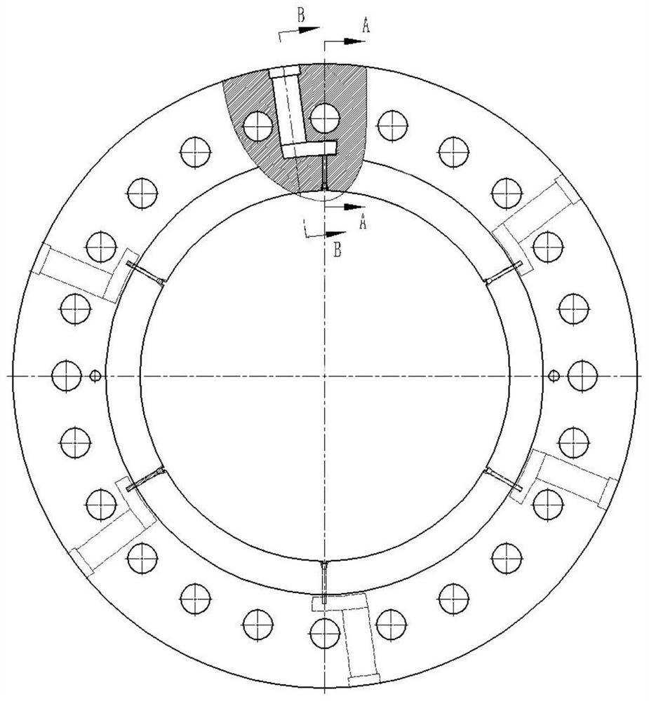
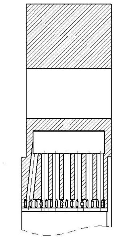
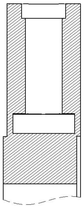
technical field [0001] The invention belongs to the technical field of precision machining, and relates to a method for welding and forming an outer ring inlet and outlet water channel of a heat exchange honeycomb structure. Background technique [0002] The outer ring of the heat exchange honeycomb structure is made of 06Cr19Ni10 forging material. This part is the flange device of the heat exchange honeycomb structure. And the inner surface of the water chamber is smooth, no excess is allowed, such as figure 1 shown. [0003] However, there are more or less problems in the current traditional process and forming methods, as follows: a) Machining and forming: five-axis machining center equipment can realize inclined hole processing, and large-scale five-axis EDM equipment can realize square water channel processing , but the fan-shaped groove cannot be realized by machining methods. b) Casting molding: precision cast steel castings can form fan-shaped grooves and square w...

Claims


Application Information

Patent Timeline
Patent Type & Authority Applications(China)
IPC IPC(8): B23P15/00B23K1/008B23K101/02
CPCB23P15/00B23K1/008B23K2101/02
Inventor 王程成任耀文周伟超李淑芳
Owner XIAN YUANHANG VACUUM BRAZING TECH
Why Eureka
Try Eureka