Supercharge Your Innovation With Domain-Expert AI Agents!

Hydraulic machine protection device and application method thereof

A protection device and technology for hydraulic presses, applied in the field of hydraulic presses, can solve problems such as damage to hydraulic presses, safety accidents, inconvenience in use, etc., and achieve the effects of improving maintenance safety, prolonging service life, and simple and convenient operation.

Active Publication Date: 2021-02-09
中建三局科创产业发展有限公司
View PDF7 Cites 0 Cited by
  • Summary
  • Abstract
  • Description
  • Claims
  • Application Information

AI Technical Summary

Problems solved by technology

[0003] The sliding table slide protection of the existing hydraulic press is applied in the working process of the hydraulic press, and the slide table is stopped or returned through the conversion of the electric signal, but when the power is cut off, such as when the mold is cleaned, the hydraulic machine fails, such as the slide table slides, and the protection cannot be carried out. , the upper and lower platens collide together, which can easily cause damage to the hydraulic machine, thereby increasing the cost of equipment maintenance and updating for users, and even causing safety accidents, which is not easy to use
[0004] A hydraulic machine protection structure and its use method are disclosed in the invention patent specification whose patent number is CN111452419A. Although it has the effect of protecting the hydraulic machine to a certain extent, there are many parts used, the structure is complicated, and it is not convenient to use.

Method used


Image

  • Hydraulic machine protection device and application method thereof
  • Hydraulic machine protection device and application method thereof
  • Hydraulic machine protection device and application method thereof

Examples


Embodiment Construction

[0028] The following will clearly and completely describe the technical solutions in the embodiments of the present invention with reference to the accompanying drawings in the embodiments of the present invention. Obviously, the described embodiments are only some, not all, embodiments of the present invention. Based on the embodiments of the present invention, all other embodiments obtained by persons of ordinary skill in the art without making creative efforts belong to the protection scope of the present invention.

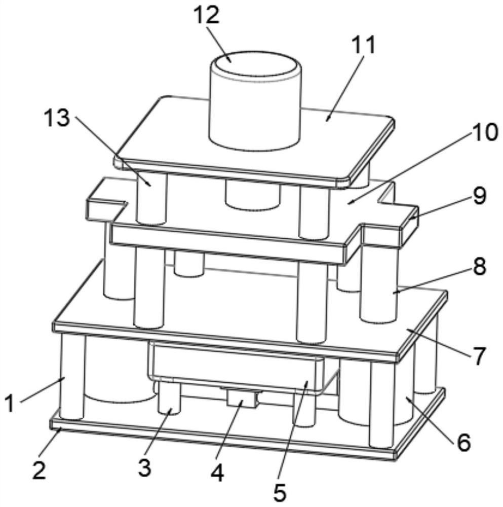
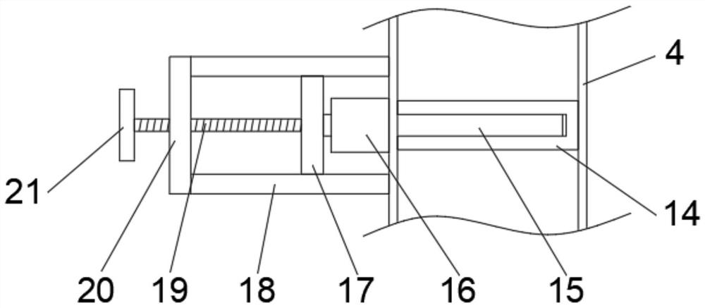
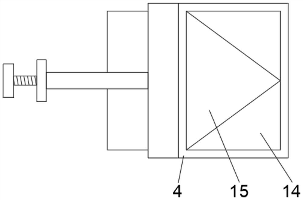
[0029] see Figures 1 to 4 , in an embodiment of the present invention, a hydraulic machine protection device includes a base 2, a support platform 7 installed on the base 2, and a top plate 11 installed on the support platform 7. The four corners of the bottom surface of the top plate 11 are respectively connected to a vertical The top of the vertically installed guide rod 13 is fixedly connected, the bottom of the guide rod 13 is fixedly connected with the u...


PUM


Abstract

The invention discloses a hydraulic machine protection device and an application method of the hydraulic machine protection device, and relates to the field of hydraulic machines. The device specifically comprises a base, a supporting platform installed on the base and a top plate installed on the supporting platform. A vertical hydraulic cylinder is welded and fixed to the top plate, the hydraulic cylinder is fixedly connected with the top end of a hydraulic rod, and the bottom end of the hydraulic rod is fixedly connected with the middle of the top surface of a lifting platform which is horizontally installed; connecting blocks are symmetrically and integrally formed and fixed to the two sides of the lifting platform, and the bottom surfaces of the connecting blocks are correspondingly and fixedly connected with the top ends of piston rod which are vertically installed; and the bottom ends of the piston rods stretch into piston cylinders and are connected with the piston cylinders ina sliding mode, the bottom ends of the side faces of the piston cylinders are fixedly connected with the bottom ends of the two sides of a square pipe through connecting pipes correspondingly, and the top end of the square pipe is fixedly connected with the bottom end of a hydraulic box. In the overhauling process of a hydraulic machine, a rotary disc is rotated to enable a sealing plate to completely seal a sealing base, hydraulic oil cannot circulate, and therefore the piston rods are fixed, and the overhauling safety of the hydraulic machine is improved.

Description

technical field [0001] The invention relates to the field of hydraulic machines, in particular to a protective device for hydraulic machines and a method for using the same. Background technique [0002] A hydraulic press is a machine that uses liquid as a working medium and is made according to Pascal's principle to transfer energy to realize various processes. A hydraulic press generally consists of three parts: the machine (main machine), the power system and the hydraulic control system. Hydraulic presses are classified into valve hydraulic presses, liquid hydraulic presses, and engineering hydraulic presses. [0003] The sliding table slide protection of the existing hydraulic press is applied in the working process of the hydraulic press, and the slide table is stopped or returned through the conversion of the electric signal, but when the power is cut off, such as when the mold is cleaned, the hydraulic machine fails, such as the slide table slides, and the protectio...

Claims


Application Information

Patent Timeline
Patent Type & Authority Applications(China)
IPC IPC(8): B30B15/28
CPCB30B15/287
Inventor 徐良
Owner 中建三局科创产业发展有限公司
Features
  • R&D
  • Intellectual Property
  • Life Sciences
  • Materials
  • Tech Scout
  • Unparalleled Data Quality
  • Higher Quality Content
  • 60% Fewer Hallucinations
Learn More