Vehicle error state updating method and device
An error and vehicle technology, applied in the field of vehicle error status update, can solve problems such as unfavorable unmanned vehicle positioning
- Summary
- Abstract
- Description
- Claims
- Application Information
AI Technical Summary
Problems solved by technology
Method used
Image
Examples
Embodiment 1
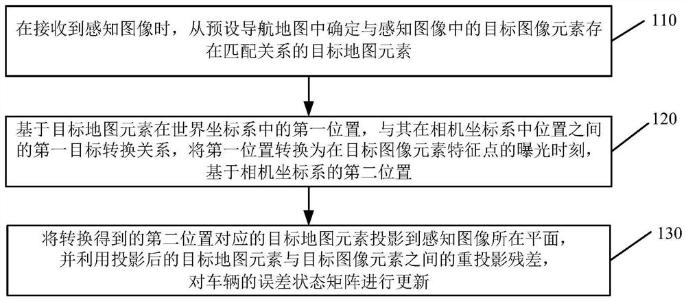
[0144] see image 3 , image 3 It is a schematic flowchart of a method for updating a vehicle error state provided by an embodiment of the present invention. This method is applied to the application scenario where a rolling shutter camera is used as a sensing device for automatic driving, and can be executed by a device for updating vehicle error state quantities. In a vehicle-mounted terminal such as an industrial personal computer (Industrial personal Computer, IPC), the embodiments of the present invention are not limited. Such as image 3 As shown, the method provided in this embodiment specifically includes:
[0145] 110. When the perception image is received, determine a target map element that has a matching relationship with the target image element in the perception image from the preset navigation map.
[0146] Wherein, the perceptual image is obtained by using a preset perceptual model to recognize the image including road information collected by the camera. ...
Embodiment 2
[0177] see Figure 4 , Figure 4 It is a schematic flowchart of a method for updating a vehicle error state provided by an embodiment of the present invention. In this embodiment, on the basis of the above embodiments, the light pole is used as the target map element, and the process of calculating the reprojection residual and solving the coefficient matrix is optimized. Such as Figure 4 As shown, the method includes:
[0178] 210. When the perception image is received, determine a target map element that has a matching relationship with the target image element in the perception image from the preset navigation map.
[0179] In this embodiment, the target map element and the corresponding target sensing element are preferably streetlight poles.
[0180] 220. Based on the first target conversion relationship between the first position of the target map element in the world coordinate system and its position in the camera coordinate system, convert the first position to...
Embodiment 3
[0204] see Figure 5 , Figure 5 It is a schematic flowchart of a method for updating a vehicle error state provided by an embodiment of the present invention. In this embodiment, on the basis of the above embodiments, traffic signs are used as target map elements, and the process of calculating the reprojection residual and solving the coefficient matrix is optimized. Such as Figure 5 As shown, the method includes:
[0205] 310. When the perception image is received, determine a target map element that has a matching relationship with the target image element in the perception image from the preset navigation map.
[0206] In this embodiment, the target map element and the corresponding target perception element are preferably traffic signs.
[0207] 320. Based on the first target conversion relationship between the first position of the target map element in the world coordinate system and its position in the camera coordinate system, convert the first position to the...
PUM
 Abstract
Description
Claims
Application Information
 - R&D
- Intellectual Property
- Life Sciences
- Materials
- Tech Scout
- Unparalleled Data Quality
- Higher Quality Content
- 60% Fewer Hallucinations
Browse by: Latest US Patents, China's latest patents, Technical Efficacy Thesaurus, Application Domain, Technology Topic, Popular Technical Reports.
© 2025 PatSnap. All rights reserved.Legal|Privacy policy|Modern Slavery Act Transparency Statement|Sitemap|About US| Contact US: help@patsnap.com


