Broadband noise reduction structure applied to natural ventilation soundproof window and design method of broadband noise reduction structure

A natural ventilation and sound-insulating window technology, which is applied in ventilation layout, door/window application, sound-proof door/window, etc., can solve the problem of low frequency ineffectiveness, achieve low cost, increase noise reduction, and work stably

Pending Publication Date: 2021-02-09
NANJING UNIV
View PDF4 Cites 0 Cited by
  • Summary
  • Abstract
  • Description
  • Claims
  • Application Information

AI Technical Summary

Problems solved by technology

A number of grooves of different sizes are arranged on the inner wall of the annular airflow main pipe to form a broadband muffler to realize broadband control of pipeline noise, but the effective working frequency band of this structure is above 1000Hz, and it does not work for low frequencies (CN202832715U)

Method used


Image

  • Broadband noise reduction structure applied to natural ventilation soundproof window and design method of broadband noise reduction structure
  • Broadband noise reduction structure applied to natural ventilation soundproof window and design method of broadband noise reduction structure
  • Broadband noise reduction structure applied to natural ventilation soundproof window and design method of broadband noise reduction structure

Examples


Embodiment example 1

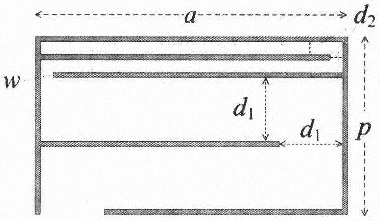
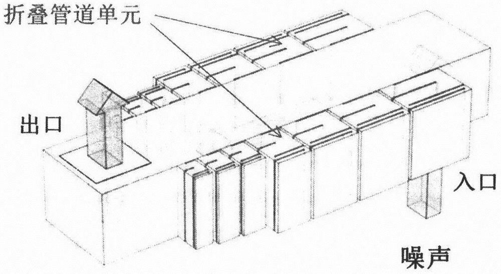
[0028] Implementation Case 1 is carried out in a staggered window of 1.5m×0.32m×0.25m, and the size of the entrance and exit are both 0.2m×0.2m, see attached Figure 4 . Seven different folded pipe units are designed for seven central frequencies. The specific frequencies and structural dimensions are shown in Table 1. The total structural size is 1.018m×0.25m×0.175m. The structure is introduced symmetrically on the pipe 2 side, see attached image 3 . When the incident noise is a normal incident plane wave with an amplitude of 1Pa, the sound pressure level at 10cm away from the center of the outlet before and after introducing the structure is shown in the appendix Figure 5 . attached Figure 5 Most frequencies between 100Hz-500Hz have noise reduction, and the total sound pressure level is 8.8dB. attached Figure 6 The sound pressure level at the evaluation point between 100Hz-2000Hz is given, and the conclusion is the same as Figure 5 Similarly, almost all frequenci...

Embodiment example 2

[0031] Implementation case 2 is carried out in a staggered window of 375mm×80mm×62.5mm, and the size of the entrance and exit is 50mm×50mm. This model is a 1:4 scale model of the staggered window in implementation case 1. The experimental photos are attached Figure 7 . The staggered window model is installed on a 1.2m×1.1m×1.0m sound insulation box located in the anechoic room. Design 7 different folded pipe units for 7 center frequencies. The specific frequencies and structural dimensions are shown in Table 2. The total structural size is 222.0mm×62.5mm×50.0mm, obtained by 3D printing of ABS plastic, see the attached Figure 8 . All folded pipe units are symmetrically introduced on the side of the staggered window scale model 2 to reduce the noise radiated from the sound source inside the sound insulation box. See attached Figure 9 . attached Figure 9 Almost all frequencies between 400Hz-6400Hz have noise reduction, and the total sound pressure level is 12.6dB.

[00...


PUM


Abstract

The invention discloses a folding pipeline type broadband noise reduction structure and a design method thereof. The folding pipeline type broadband noise reduction structure is installed on the sidewall of a ventilation path of a natural ventilation staggered sound insulation window, and each folding pipeline unit is formed by coupling two rectangular pipelines with different sectional areas; and a plurality of folding pipeline units designed for different frequencies are combined to achieve broadband noise reduction of noise transmitted into the window. By means of the structure, the low-frequency noise reduction amount of the staggered sound insulation window is effectively increased, and compared with a traditional active control technology for low-frequency noise reduction, the structure is convenient to install, simple in system and stable in work and has the noise reduction effect at medium-high frequency.

Description

[0001] 1. Technical field [0002] The invention relates to a broadband noise reduction structure applied to natural ventilation staggered sound insulation windows and its design method. A series of folded duct units designed for different frequencies are introduced on the side of the ventilation path 2 of the staggered sound insulation windows, which can realize the transmission of noise through the windows. Broadband noise reduction for incoming noise. [0003] 2. Background technology [0004] With the development of society, traffic noise pollution has become one of the main urban pollution. Windows can be closed to reduce incoming traffic noise from the outside, but this affects indoor ventilation. A sound insulation window with a staggered structure can effectively reduce 125Hz-8000Hz noise while lighting and ventilating (CN103075088A); adding micro-perforated plates to the staggered window can further improve the passive noise reduction for medium and high frequency noi...

Claims


Application Information

Patent Timeline
Patent Type & Authority Applications(China)
IPC IPC(8): G06F30/18G06F30/23E06B5/20E06B7/02G06F113/14G06F119/10
CPCE06B5/205E06B7/02G06F30/18G06F30/23G06F2113/14G06F2119/10
Inventor 王淑萍陶建成邱小军
Owner NANJING UNIV
Why Eureka
Try Eureka