
Blending device for lubricating oil production

A lubricating oil and blending technology is applied in the field of blending devices for lubricating oil production.

Active Publication Date: 2021-02-12
山东莱克科技有限公司
View PDF11 Cites 0 Cited by
  • Summary
  • Abstract
  • Description
  • Claims
  • Application Information

AI Technical Summary

Problems solved by technology

However, in the above-mentioned patents, the relative change of the stirring mechanism and the mixing cylinder is relatively simple, and the direction is relatively single, and the design of the stirring mechanism itself is relatively simple, resulting in an unsatisfactory blending effect, so there are certain limitations.

Method used


Image

  • Blending device for lubricating oil production
  • Blending device for lubricating oil production
  • Blending device for lubricating oil production

Examples


Embodiment 1

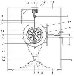
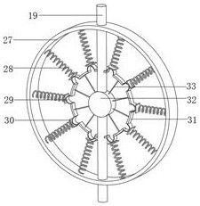
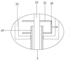
[0030] refer to Figure 1-4 , a blending device for lubricating oil production, comprising a base 4 with legs welded at the four corners of the bottom outer wall, booms 5 are vertically welded on both sides of the top outer wall of the base 4, and the top of the boom 5 is welded with the same ejector rod 11 , one side of the outer wall of the boom 5 is fixed with a push rod motor 8 by bolts, and the end of the extension rod of the push rod motor 8 is fixed with a connecting end block 9 by bolts, and the connecting end block 9 is slidably connected with a connecting end plate 10, And one side connecting the end plate 10 is welded with a blending tank 2, and the four corners of the bottom outer wall of the blending tank 2 are welded with a support frame 24, and the bottom end of the support frame 24 is welded with the same mounting block 25, and the bottom end of the mounting block 25 rotates A pulley 26 is connected, and the top outer wall of the base 4 is fixed with a corrugat...

Embodiment 2

[0041] refer to figure 1 and Figure 5 , a blending device for lubricating oil production. Compared with Embodiment 1, this embodiment also includes liquid turning plates 39 that are welded to the outer peripheral wall of the liquid-draining ring 37 and are alternately distributed with the pendulum blades 22 .

[0042] When the present invention is used: using the liquid turning plate 39 arranged on the outer wall of the liquid dialing ring 37, when the position of the mixing tank 2 and the mixing mechanism in the vertical direction changes, the stirring of the material in the vertical direction by the mixing mechanism can be further improved effect, in order to further improve the harmonization effect of the device.


PUM


Abstract

The invention belongs to the technical field of lubricating oil production, particularly relates to a blending device for lubricating oil production, and provides the following scheme for solving theproblems that in the traditional lubricating oil production process, a blending device is simple in design, the relative position of a blending mechanism and a material bearing part is fixed, and theblending effect on liquid materials is common. The device comprises a base, supporting legs are welded to the four corners of the outer wall of the bottom of the base, arm supports are vertically welded to the two sides of the outer wall of the top of the base, the same ejector rod is welded to the top ends of the arm supports, and a push rod motor is fixed to the outer wall of one side of one armsupport through bolts. The connecting end block, the connecting end plate and the pulley can be used for driving the blending tank to move according to the rail groove in the waveform block, and themoving block is driven to move under the action of the swing column, the sleeve and the y-shaped rod, so that the change of the relative position of the blending tank and the mixing mechanism is realized, and the oscillation of materials is facilitated; therefore, the action effect of the mixing mechanism is improved.

Description

technical field [0001] The invention relates to the technical field of lubricating oil production, in particular to a blending device for lubricating oil production. Background technique [0002] Lubricating oil is a liquid or semi-solid lubricant used in various types of automobiles and mechanical equipment to reduce friction and protect machinery and processed parts. It mainly plays the roles of lubrication, auxiliary cooling, rust prevention, cleaning, sealing and buffering. As long as it is applied between two relatively moving objects and can reduce the friction and wear of the two objects due to the function of contact, it is a lubricating oil. Lubricating oil generally consists of two parts: base oil and additives. Base oil is the main component of lubricating oil, which determines the basic properties of lubricating oil. Additives can make up for and improve the performance of base oil, endow some new properties, and are an important part of lubricating oil. [000...

Claims


Application Information

Patent Timeline
IPC IPC(8): B01F11/00B01F15/00
CPCB01F31/20B01F31/56B01F35/31B01F35/3204B01F2101/39
Inventor 黄莉
Owner 山东莱克科技有限公司
Learn More