Construction site steel pipe surface cleaning equipment

A surface cleaning and steel pipe technology, which is applied in the direction of removing smoke and dust, cleaning hollow objects, cleaning methods and utensils, etc., can solve the problems of high labor intensity, many cleaning steps, and slow cleaning speed, so as to reduce labor intensity and ensure scraping Effect, ensure the effect of scraping evenly

Active Publication Date: 2021-02-12
巢湖市鼎力铁塔有限公司
View PDF5 Cites 7 Cited by
  • Summary
  • Abstract
  • Description
  • Claims
  • Application Information

AI Technical Summary

Problems solved by technology

[0005] 1. The existing methods are usually manual beating and removal, which is time-consuming and labor-intensive, and the removal effect is poor, the labor intensity is high, and the noise is relatively loud. The dust generated during beating is easily inhaled by workers, which is not conducive to their cardiopulmonary health.
[0006] 2. The existing cleaning devices are large in size, high in cost, large in number of driving parts, and high in power consumption, which is not conducive to reducing cleaning costs. At the same time, there are many cleaning steps, the cleaning speed is slow, and the dust after cleaning cannot be collected, which is easy Staying inside the device will cause pollution and easily cause blockage of the device, thus affecting the subsequent use of the device

Method used


Image

  • Construction site steel pipe surface cleaning equipment
  • Construction site steel pipe surface cleaning equipment
  • Construction site steel pipe surface cleaning equipment

Examples


Embodiment Construction

[0043] The technical solutions of the present invention will be further described below in conjunction with the accompanying drawings and through specific implementation methods.

[0044] Wherein, the accompanying drawings are only for illustrative purposes, showing only schematic diagrams, rather than physical drawings, and should not be construed as limitations on this patent; in order to better illustrate the embodiments of the present invention, some parts of the accompanying drawings will be omitted, Enlarged or reduced, does not represent actual product size.

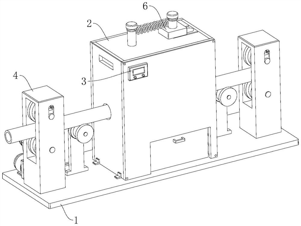
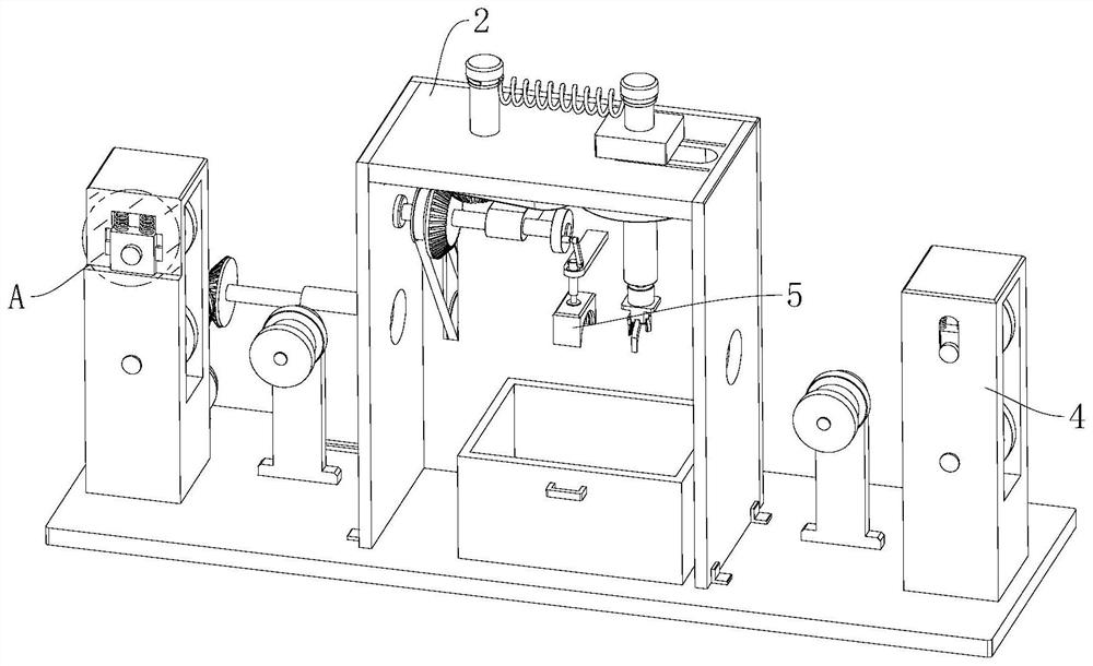
[0045] refer to Figure 1 to Figure 10 A construction site steel pipe surface cleaning equipment shown includes a base 1 and a cleaning box 2, the base 1 is arranged horizontally, and the cleaning box 2 is fixed on the top of the base 1, and also includes a controller 3, a conveying mechanism 4, Beating mechanism 5 and scraping mechanism 6, described controller 3 is fixedly arranged on the outer wall of cleaning ...


PUM


Abstract

The invention relates to the field of cleaning devices, in particular to construction site steel pipe surface cleaning equipment. The equipment comprises a base and a cleaning box and further comprises a controller, a conveying mechanism, a beating mechanism and a scraping mechanism. The conveying mechanism is arranged at the top of the base to be used for conveying steel pipes and comprises a transmission assembly and two conveying tables. The beating mechanism is arranged at the top of the inner side of the cleaning box and used for beating the steel pipes, the beating mechanism comprises ahammer head and a rotating assembly, the scraping mechanism is arranged at the top of the inner side of the cleaning box and used for scraping impurities such as concrete on the surfaces of the steelpipes, the scraping mechanism comprises a scraping head, a pushing assembly and a limiting assembly, and the transmission assembly is electrically connected with the controller. According to the construction site steel pipe surface cleaning equipment, manpower is automatically replaced, the cleaning efficiency is high, the labor intensity is low, the noise is low, meanwhile, the power consumptionis low, the cleaning cost can be reduced, the cleaned impurities can be effectively collected, and pollution is avoided.

Description

technical field [0001] The invention relates to the field of cleaning devices, in particular to a steel pipe surface cleaning device on a construction site. Background technique [0002] Steel pipe, having a hollow section whose length is much greater than its diameter or circumference. According to the cross-sectional shape, it is divided into circular, square, rectangular and special-shaped steel pipes; according to the material, it is divided into carbon structural steel pipes, low alloy structural steel pipes, alloy steel pipes and composite steel pipes; Steel pipes for thermal equipment, petrochemical industry, machinery manufacturing, geological drilling, high-pressure equipment, etc.; according to the production process, they are divided into seamless steel pipes and welded steel pipes, among which seamless steel pipes are divided into hot-rolled and cold-rolled (drawn) Two kinds, welded steel pipe is divided into straight seam welded steel pipe and spiral seam welde...

Claims


Application Information

Patent Timeline
Patent Type & Authority Applications(China)
IPC IPC(8): B08B9/023B08B15/00
CPCB08B9/023B08B15/00B08B2209/02Y02P70/10
Inventor 徐茂坤
Owner 巢湖市鼎力铁塔有限公司
Why Eureka
Try Eureka