Processing system for steel pipe filled concrete

A processing system and concrete technology, which is applied in the direction of clay preparation device, mixing operation control, mixing operation control device, etc., can solve the problems of low mixing efficiency, low operating efficiency, poor quality, etc., and achieve reasonable structural design, fast and efficient production, The effect of high stirring efficiency

Active Publication Date: 2021-02-12
桐乡市钟大建材有限公司
View PDF8 Cites 2 Cited by
  • Summary
  • Abstract
  • Description
  • Claims
  • Application Information

AI Technical Summary

Problems solved by technology

In the production and preparation process of the existing steel pipe filling concrete, it is necessary to transfer the various ingredients of the prepared concrete to the mixing tank in proportion and then mix them uniformly. It is difficult for the existing mixing equipment for preparing the mixing tank to fully and efficiently mix the various ingredients. Uniform, long-term stirring is required to complete the preparation and processing of concrete, resulting in low mixing efficiency and poor quality of preparation and processing of concrete preparation and processing. The existing steel pipe filling concrete can produce micro-expansion during the hydration period of concrete, so as to compensate The shrinkage of concrete achieves the purpose of preventing concrete cracks and improving the performance of concrete...

Method used


Image

  • Processing system for steel pipe filled concrete
  • Processing system for steel pipe filled concrete
  • Processing system for steel pipe filled concrete

Examples


Embodiment Construction

[0027]In order to further describe the present invention, a specific implementation of a steel pipe-filled concrete processing system is further described below with reference to the accompanying drawings. The following examples are for explaining the present invention and the present invention is not limited to the following examples.

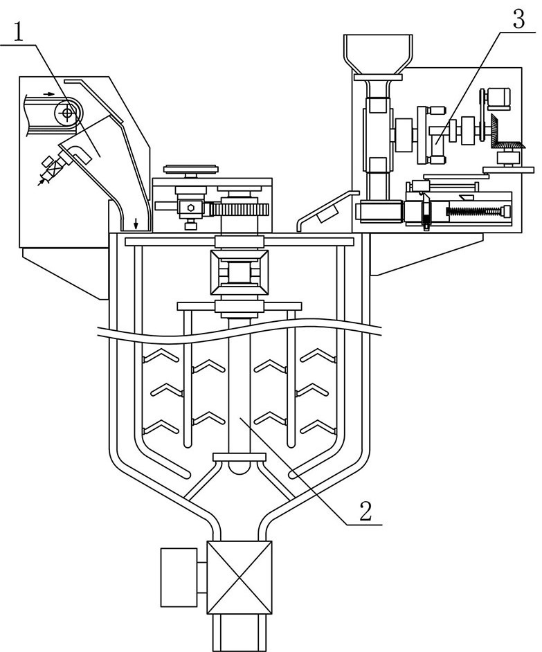
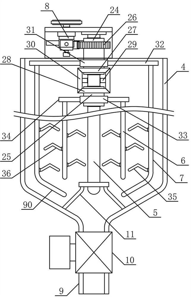
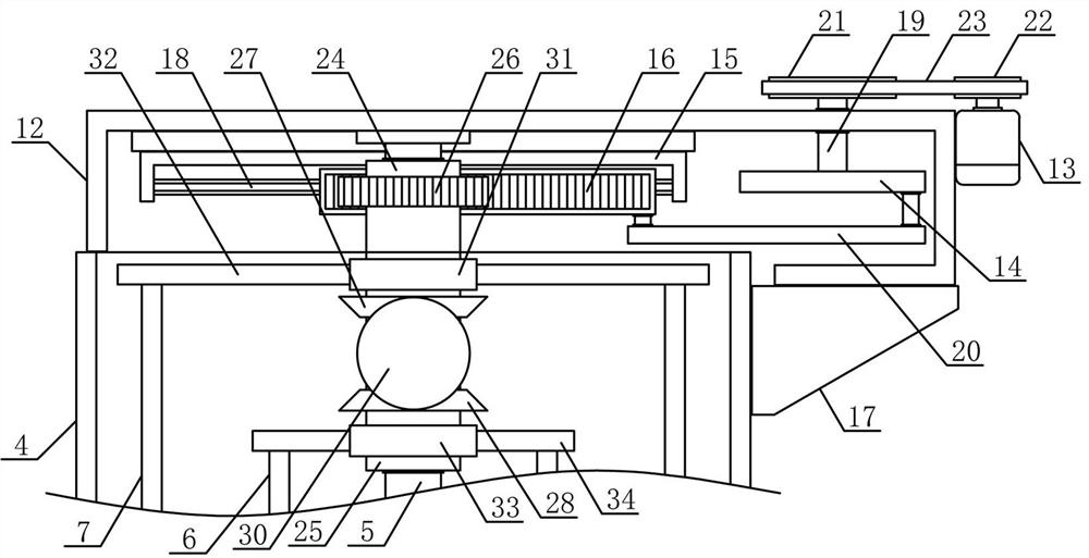
[0028]Such asfigure 1 As shown, a processing system for steel pipe stuffing concrete of the present invention includes a main material conveying mechanism 1, a processing mixing mechanism 2 and an auxiliary material filling mechanism 3. The main material conveying mechanism 1 and auxiliary material filling mechanism 3 are respectively arranged in the processing and mixing mechanism 2 The upper sides, such asfigure 2 withimage 3 As shown, the processing stirring mechanism 2 of the present invention includes a preparation stirring tank 4, a stirring support column 5, a processing inner stirring rod 6, a processing outer stirring rod 7 and a stirring driv...


PUM


Abstract

The invention discloses a processing system for steel pipe filled concrete, and belongs to the field of building material processing mechanical equipment. A main material conveying mechanism and an auxiliary material filling mechanism are arranged on the two sides of the upper portion of a processing stirring mechanism, a stirring driving mechanism of the processing stirring mechanism is fixedly arranged on the upper side of a preparation stirring tank, processing outer stirring rods are arranged on the lower sides of the outer ends of a plurality of outer stirring supporting connecting plateson the outer side of an outer stirring fixing sleeve, processing inner stirring rods are vertically and fixedly arranged on the lower sides of the outer ends of a plurality of inner stirring supporting connecting plates on the outer side of an inner stirring fixing sleeve, a feeding guide pipe is arranged on a main material conveying support, auxiliary material storage grooves are formed in the two sides of a guide rotating disc respectively, and an auxiliary material pushing mechanism is arranged on an auxiliary material guide support on the adjacent side of an auxiliary material filling guide pipe. The processing system for steel pipe filled concrete is reasonable in structural design, can be used for quickly and efficiently producing and preparing the steel pipe filled concrete, can beused for conveniently and accurately adding production auxiliary materials as required, is high in processing automation degree and meets the requirements of production and use.

Description

Technical field[0001]The invention belongs to the field of building material processing machinery and equipment, and in particular relates to a processing system for steel pipe stuffing concrete, which is mainly applied to the production and preparation of steel pipe stuffing concrete.Background technique[0002]Concrete refers to the general term of engineering composite materials that cement aggregates into a whole by cementing materials. Concrete is the most important contemporary civil engineering material. It is composed of cementing materials, granular aggregates, water, admixtures and admixtures. The material is prepared in a certain proportion, uniformly mixed, compacted, formed, and cured to form an artificial building material. The concrete has the characteristics of abundant raw materials, low price, and simple production process, so the usage is increasing. There are many types of concrete. Concrete filled with steel pipes is the main type of concrete. Concrete filled with...

Claims


Application Information

Patent Timeline
IPC IPC(8): B28C5/16B28C5/08B28C7/06B28C7/04B28C7/12
CPCB28C5/16B28C5/0831B28C5/0818B28C7/06B28C7/0459B28C7/0463B28C7/126
Inventor 黄建新沈永明
Owner 桐乡市钟大建材有限公司
Why Eureka
Try Eureka