
Oil-water separation device for chemical machinery

A technology of oil-water separation device and chemical machinery, which is applied in liquid separation, separation method, grease/oily substance/float removal device, etc., can solve the problems of poor separation effect, remixing of oil and water, high suction force, etc., to improve convenience sexual effect

Inactive Publication Date: 2021-02-12
西安汇龙中鼎机械设备有限公司
View PDF0 Cites 0 Cited by
  • Summary
  • Abstract
  • Description
  • Claims
  • Application Information

AI Technical Summary

Problems solved by technology

[0004] The purpose of the present invention is to solve the problem in the prior art that after the oil layer and the water layer are separated by the gravity separation method and the air flotation separation method, the water and the oil layer need to be extracted separately through the pump body, but in the actual use process, due to the When the body is pumped out of the oil layer or water layer, it will generate a large suction force, which will cause part of the oil and water to remix, resulting in the problem of poor separation effect. An oil-water separation device for chemical machinery is proposed.

Method used


Image

  • Oil-water separation device for chemical machinery
  • Oil-water separation device for chemical machinery
  • Oil-water separation device for chemical machinery

Examples


Embodiment Construction

[0020] The following will clearly and completely describe the technical solutions in the embodiments of the present invention with reference to the accompanying drawings in the embodiments of the present invention. Obviously, the described embodiments are only some, not all, embodiments of the present invention.

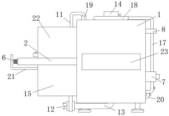
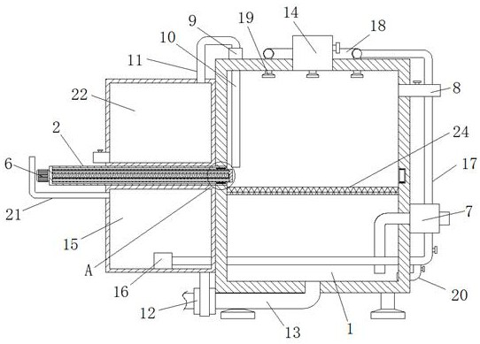
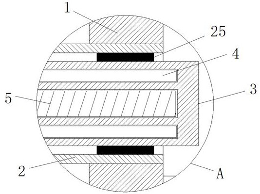
[0021] refer to Figure 1-3 , an oil-water separation device for chemical machinery, comprising a separation box 1, the left side wall of the separation box 1 is fixedly connected with a support plate 2, the right side wall of the support plate 2 is provided with a storage tank, and the inside of the storage tank is slidingly connected with a gate 3. The upper and lower ends of the bottom of the storage tank are fixedly connected with the sliding rod 4, and the upper and lower ends of the left side wall of the gate 3 are provided with chute matching the sliding rod 4, and the bottom of the storage tank is located at two The position between the slide rods 4 is connec...


PUM


Abstract

The invention relates to the technical field of chemical sewage treatment, and discloses an oil-water separation device for chemical machinery. The device comprises a separation box, a supporting plate is fixedly connected to the left side wall of the separation box, a storage groove is formed in the right side wall of the supporting plate, a flashboard is slidably connected into the storage groove, and sliding rods are fixedly connected to the upper end and the lower end of the groove bottom of the storage groove. Sliding grooves matched with the sliding rods are formed in the upper end and the lower end of the left side wall of the gate plate correspondingly, and a threaded rod is rotatably connected to the position, located between the two sliding rods, of the groove bottom of the storage groove through a bearing. According to the oil-water separation device, the oil-water layering position can be sealed and separated, the situation that the separation effect is affected due to re-mixing of part of oil and water caused by suction force during pumping is avoided, meanwhile, people can wash the interior of the separation box conveniently, cleaning inconvenience caused by attachment and condensation of part of oil drops is avoided, people can adjust the oil-water layering position conveniently, and use is convenient.

Description

technical field [0001] The invention relates to the technical field of chemical sewage treatment, in particular to an oil-water separation device for chemical machinery. Background technique [0002] In petrochemical, marine engineering, mechanical processing and other industries, because of the production process, wastewater containing oil is often produced. These wastewater must be purified before discharge, especially oil-water separation is particularly important. [0003] At present, the oil-water separation methods commonly used in the field of chemical machinery include gravity separation, centrifugal separation, electrolysis separation, air flotation separation, etc. Among them, the air flotation separation method has a better effect on oil-water separation and has higher efficiency and is more commonly used. , after the oil layer and water layer are separated by gravity separation method and air flotation separation method, the water and oil layer need to be pumped ...

Claims


Application Information

Patent Timeline
IPC IPC(8): C02F1/24C02F1/40
CPCC02F1/24C02F1/40C02F2303/14
Inventor 陈笑芝张广权焦挺
Owner 西安汇龙中鼎机械设备有限公司
Learn More