Method and device for removing oil by cold air flotation

An air flotation degreasing and cooling technology, which is applied in the direction of grease/oily substance/suspton removal devices, separation methods, chemical instruments and methods, etc., can solve unfavorable environmental protection, chemical agent residue, and small concentration range of oil content in air flotation treatment and other problems to achieve the effect of increasing air flotation efficiency and reducing usage

Pending Publication Date: 2021-02-12
EAST CHINA UNIV OF SCI & TECH
View PDF7 Cites 3 Cited by
  • Summary
  • Abstract
  • Description
  • Claims
  • Application Information

AI Technical Summary

Problems solved by technology

However, the traditional air flotation method is often used in combination with chemical agents, resulting in a large amount of chemical agents remaining in the production water, which is not conducive to environmental protection
[0004] CN102626560A discloses a cyclone air flotation oil-water separation device and an air flotation generator, which has a simple structure and solves the shortcoming of the small concentration range of oil content in air flotation treatment
However, the above patented technologies are all optimized and modified for the structure of the air flotation device, and no technical improvements have been made for the characteristics that the solubility of oil in water is affected by temperature.

Method used


Image

  • Method and device for removing oil by cold air flotation
  • Method and device for removing oil by cold air flotation
  • Method and device for removing oil by cold air flotation

Examples


Embodiment 1

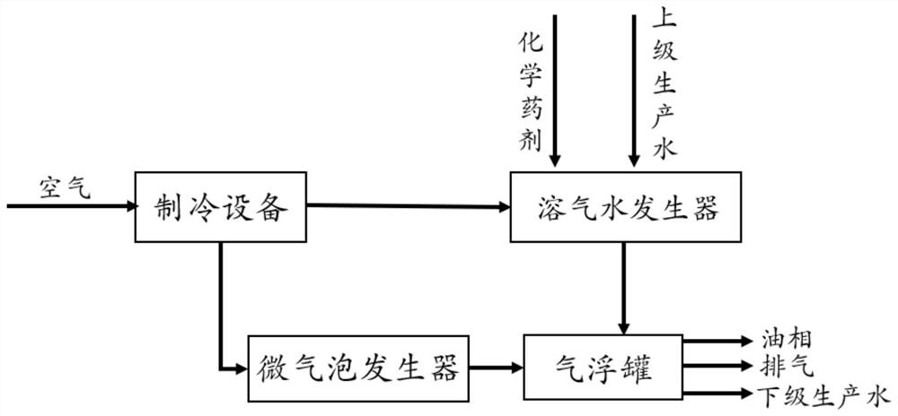
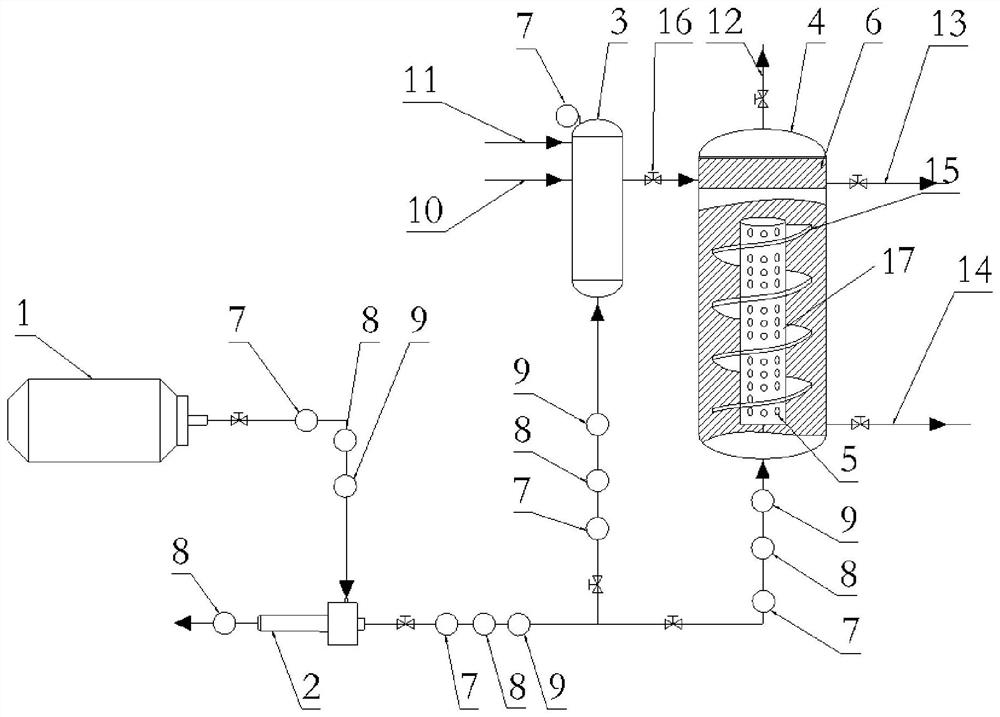
[0035] Such as figure 1 and figure 2 As shown, the cold air flotation degreasing method of the present embodiment comprises the following steps:

[0036] The air or the compressed air compressed by the compressor 1 is introduced into the refrigeration equipment (the vortex tube 2 is used here), and the cold air prepared by the refrigeration equipment is divided into two paths, wherein the first cold air leads to the dissolved air containing the produced water The water generator 3, the second cold air leads to the air flotation tank 4 through the micro-bubble generator 5; the production water enters the dissolved air water generator 3 through the production water inlet 11.

[0037] Dissolved oil is precipitated from the production water under the action of the first cold air, and the first cold air is dissolved into the production water under high pressure (the pressure is measured by the pressure gauge 7), and chemical agents are added (the concentration range can be change...

Embodiment 2

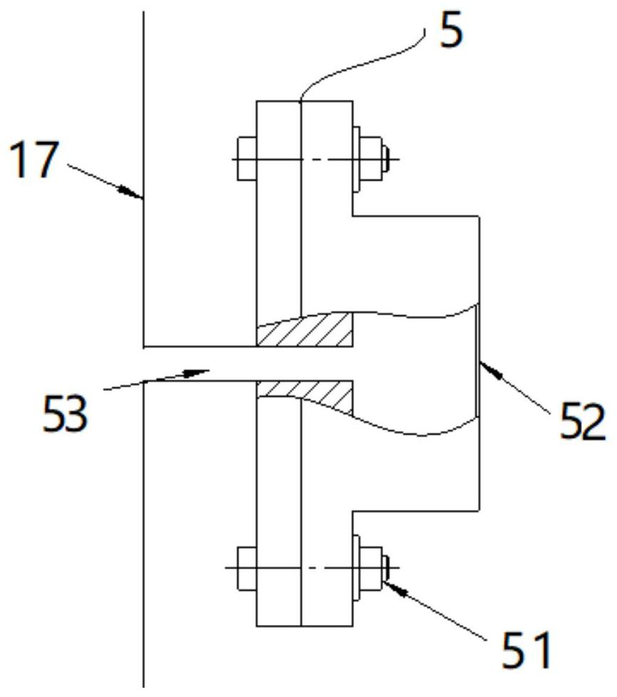
[0044] Such as figure 1 and figure 2 As shown, the cold air flotation and degreasing device of the present embodiment includes refrigeration equipment, dissolved air water generator 3 and air storage tank 17 (top seal, bottom connecting pipeline) that are connected with refrigeration equipment respectively, and there are multiple openings on the air storage tank 17. A vertically evenly distributed installation hole, the installation hole is fixed with a microbubble generator 5; the air storage tank 17 is vertical and is located in the air flotation tank 4, and the top of the air flotation tank 4 communicates with the dissolved air water generator 3, and the gas storage tank 17 The top of the floating tank 4 has a gas phase outlet 12, the upper part of the air floating tank 4 has an oil phase outlet 13, and the bottom of the air floating tank 4 has a produced water outlet 14.

[0045] Further, the dissolved air water generator 3 is connected to the pressurization equipment, a...


PUM


Abstract

The invention provides a method and a device for removing oil by utilizing cold air flotation, the method comprises the following steps: cold air prepared by refrigeration equipment is divided into two paths, the first path of cold air is led to a dissolved air water generator containing production water, and the second path of cold air is led to an air flotation tank through a microbubble generator; wherein dissolved oil is separated out from the production water under the action of the first path of cold air, and the first path of cold air is dissolved into the production water under high pressure and released into the air floatation tank through a pressure reducing valve; the second path of cold air generates low-temperature micro-bubbles in the micro-bubble generator, and the low-temperature micro-bubbles enter the air floatation tank to further separate out dissolved oil in the production water; the dissolved-state oil is adhered to the microbubbles, rises and is discharged through the air floatation tank; and the treated production water is discharged from the lower part of the air floatation tank. The device comprises refrigeration equipment, a dissolved air water generatorand a micro-bubble generator which are respectively connected with the refrigeration equipment, and an air floatation tank which is respectively connected with the dissolved air water generator and the micro-bubble generator. The device is simple in structure, economical, efficient and high in adaptability.

Description

technical field [0001] The invention belongs to the technical field of oil-water separation, and specifically relates to a method and device for oil-removing oil by cold air flotation, which is suitable for the efficient oil-removing process of produced water in the exploitation process of land and offshore oil and gas fields, and is also suitable for coal chemical industry, catering and other industries In the air flotation treatment process of oily wastewater. Background technique [0002] Today's society is still in the stage of industrial society, the world economy is in a period of rapid development as a whole, and there is a huge demand for oil and gas, but industrial production such as oil and natural gas will produce a large amount of production water, because the quality of production water in different locations is affected by the oil and gas fields. Therefore, with the increase of production age, the amount of produced water usually increases, which will lead to a...

Claims


Application Information

Patent Timeline
IPC IPC(8): C02F1/24C02F1/40
CPCC02F1/24C02F1/40C02F2209/02
Inventor 杨强李裕东刘懿谦卢浩武世汉
Owner EAST CHINA UNIV OF SCI & TECH
Why Eureka
Try Eureka