
Narrow-band level set calculation method for collaborative optimization and semi-implicit discretization of light source mask

A technology of collaborative optimization and calculation method, applied in optics, optomechanical equipment, microlithography exposure equipment, etc., can solve problems such as low computational efficiency, high computational complexity, and difficulty in applying OPC technology

Active Publication Date: 2021-02-12
GUANGDONG UNIV OF TECH
View PDF5 Cites 2 Cited by
  • Summary
  • Abstract
  • Description
  • Claims
  • Application Information

AI Technical Summary

Problems solved by technology

[0006] First, the above method optimizes and updates all observation points on the light source and mask layout during the iterative process. It needs to calculate the gradient of the spatial image and the cost function to the observation points of the light source and mask. The calculation efficiency is low, which is not conducive to large-scale Light source mask co-optimization simulation
[0007] Second, the above method uses a simple and widely used explicit discretization method, because of the limitation of the Courant-Friedrichs-Levy condition (CFL), the iteration step size is suppressed to produce excessive iterations, resulting in slow convergence; and Although the corresponding implicit discretization method overcomes the stability constraint and can use a sufficiently large iterative step size, it needs to solve a considerable scale of linear equations, which has a high computational complexity and is difficult to apply to the actual OPC technology.
[0008] In summary, the existing SMO methods need to be further improved and improved in terms of optimizing the mask frame, computational efficiency, and convergence efficiency.

Method used


Image

  • Narrow-band level set calculation method for collaborative optimization and semi-implicit discretization of light source mask
  • Narrow-band level set calculation method for collaborative optimization and semi-implicit discretization of light source mask
  • Narrow-band level set calculation method for collaborative optimization and semi-implicit discretization of light source mask

Examples


Embodiment Construction

[0067]The present invention will be further described below in conjunction with specific embodiments:

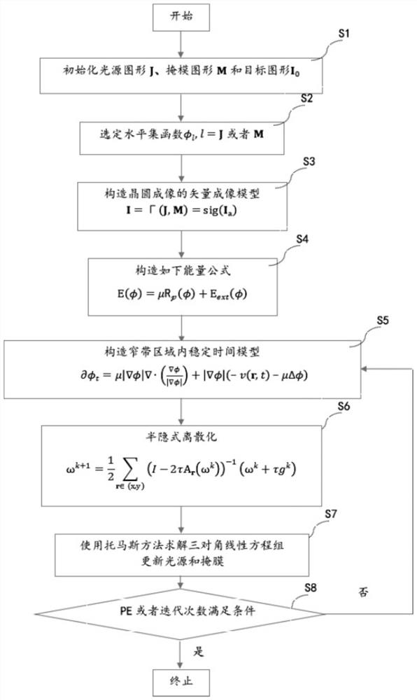
[0068]The principle of the present invention: the imaging performance and reverse recovery process of the actual projection lithography system are usually evaluated and calculated by the pattern error PE difference. In order to improve the calculation efficiency and the convergence efficiency, the cooperative optimization problem of the light source mask constructed in the present invention is an energy formula, namely:

[0069]

[0070]Among them, the first term is the distance regularization level set term to ensure the symbol distance characteristic of the level set functionThe second term is the external energy term to minimize the distortion of the mask pattern and force the optimization to proceed in the direction of reducing the pattern error PE, even if the value of the optimized aerial image at the observation point gradually approaches the value of the target circuit board diagra...


PUM


Abstract

The invention discloses a light source mask collaborative optimization semi-implicit discretization narrowband level set calculation method, and the method comprises the following steps: taking a discretized circuit board diagram variable and a discretized light source variable as observation matrixes, and taking a condition that a corresponding imaging matrix is equal to a discretized matrix of atarget pattern as a constraint condition; constructing a Lagrange equation containing a distance regularization level set item and a constraint condition to obtain a time-varying difference equation;implicitly and explicitly discretizing a diffusion term and a non-diffusion term respectively, constructing a three-diagonal linear equation set in a horizontal direction and a vertical direction byusing additive operator splitting, and performing efficient solution by using a Thomas method. According to the method, the optimization convergence efficiency can be improved while the optimization dimension is reduced.

Description

Technical field[0001]The invention relates to the technical field of optical proximity correction in the lithography resolution enhancement technology, and in particular to a narrowband level set calculation method for semi-implicit discretization of light source mask collaborative optimization.Background technique[0002]The projection lithography system is the core equipment for manufacturing micro- and nano-scale line-width ultra-large-scale integrated circuits. The projection lithography system is mainly composed of an illumination system, a mask, a projection objective, a pupil, and a silicon wafer coated with photoresist. The light waves emitted by the light source illuminate and pass through the mask to generate the near field of the mask, and project through the projection objective. The pupil’s low-pass filtering and photoresist etching transfer the mask pattern to the silicon wafer, but the loss of information in the image transfer process causes the shape on the silicon waf...

Claims


Application Information

Patent Timeline
Patent Type & Authority Applications(China)
IPC IPC(8): G03F7/20
CPCG03F7/70491G03F7/705
Inventor 沈逸江
Owner GUANGDONG UNIV OF TECH
Learn More