Casting model structure for differential mechanism shell with thick and large flange plate surface

A technology for casting models and differentials, which is applied to casting molding equipment, casting molds, cores, etc., and can solve problems such as the overall thickness of the flange surface and the side bushing area, the heavy weight of the vehicle, and unfavorable energy saving and emission reduction. , to achieve the effects of reducing product shrinkage defects, reducing shock absorption requirements, and reducing weight

Pending Publication Date: 2021-02-19
勤威(天津)工业有限公司
View PDF0 Cites 1 Cited by
  • Summary
  • Abstract
  • Description
  • Claims
  • Application Information

AI Technical Summary

Problems solved by technology

For example, in the case of the differential case in the gearbox transmission system, the flange surface and the side bushing area of ​​similar products in the past are generally relatively thick, which makes the weight of the whole vehicle relatively heavy, which is not conducive to energy saving and emission reduction.

Method used


Image

  • Casting model structure for differential mechanism shell with thick and large flange plate surface
  • Casting model structure for differential mechanism shell with thick and large flange plate surface
  • Casting model structure for differential mechanism shell with thick and large flange plate surface

Examples


Embodiment Construction

[0021] Below in conjunction with accompanying drawing and embodiment the present invention will be further described:

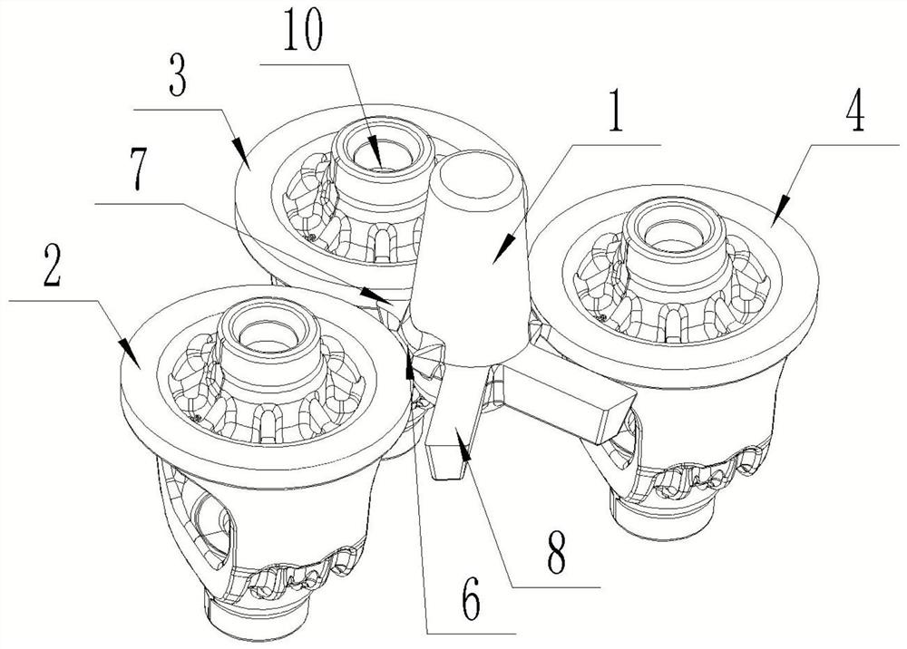
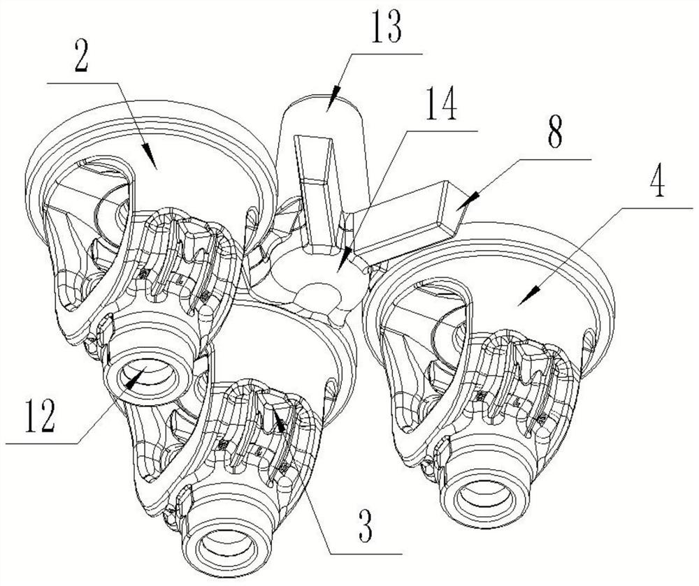
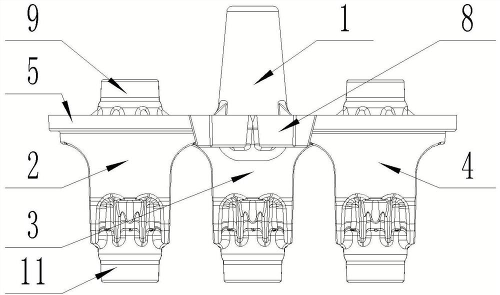
[0022] Such as Figure 1 to Figure 5 As shown, a casting model structure for a differential case with a thick and large flange surface includes a central riser column 1, and A casting 2, B casting 3 and C casting are arranged around the riser column 1. The casting 4, the A casting 2, the B casting 3, and the C casting 4 all include a flange 5 in the middle, an upper shaft sleeve 9 positioned at the top of the flange 5, and a lower shaft sleeve 11 positioned at the bottom of the flange 5, wherein A casting 2 and C casting 4 are respectively symmetrically distributed on both sides of the riser column 1, B casting 3 is on the perpendicular bisector of the line connecting the centers of A casting 2, riser column 1, and C casting 4, and the A casting 2, B casting 3 and C casting 4 are located on the same circle with the riser column 1 as the center, and there are...


PUM


Abstract

The invention discloses a casting model structure for a differential mechanism shell with a thick and large flange plate surface. The casting model structure comprises a riser column, a casting A, a casting B and a casting C are arranged on the periphery of the riser column, the casting A and the casting C are symmetrically distributed on the two sides of the riser column respectively, and the casting B is located on the perpendicular bisector of the center connecting line of the casting A, the riser column and the casting C. Connecting blocks are arranged between the riser column and flange plates of the casting A, the casting B and the casting C. First heat preservation blocks are arranged in the positions, between the casting A and the casting B and between the casting C and the castingB, of the outer wall of the riser column. A plurality of second heat preservation blocks are arranged in the positions, between the casting A and the casting C, of the outer wall of a riser, and thelength of the second heat preservation blocks is larger than that of the first heat preservation blocks. Upper shaft sleeve heat preservation columns are arranged in upper shaft sleeves of the castingA, the casting B and the casting C. Lower shaft sleeve heat preservation columns are arranged in lower shaft sleeves of the casting A, the casting B and the casting C. According to the casting modelstructure, the upper shaft sleeves, the lower shaft sleeves and the flange plate surface are thick and large, and the areas of side shaft sleeves are weaker.

Description

technical field [0001] The invention relates to the technical field of casting an automobile differential case, in particular to a casting model structure for a differential case with a large flange surface thickness. Background technique [0002] In the current environment of the automotive industry, the design of auto parts is very important, especially automotive safety components, which not only need to meet various indicators such as installation, size, performance, and frequency; With the introduction of new national policies, the design of automobile parts also needs to strengthen the control of its various indicators, such as product weight, size, and dynamic balance stability. In this way, the design of many new products will break the traditional design, and such products need to be developed and produced with more advanced and economical process solutions, and also meet their various indicators. For example, in the case of the differential case in the gearbox tra...

Claims


Application Information

Patent Timeline
Patent Type & Authority Applications(China)
IPC IPC(8): B22C9/02B22C9/08B22C9/20B22C9/22
CPCB22C9/02B22C9/082B22C9/088B22C9/20B22C9/22
Inventor 赵秀秀
Owner 勤威(天津)工业有限公司
Why Eureka
Try Eureka