Supercharge Your Innovation With Domain-Expert AI Agents!

Efficient surface rust removal device for waste steel pipe recycling

A steel pipe and high-efficiency technology, which is applied to the field of high-efficiency rust removal devices for the recycling of waste steel pipes, can solve the problems of low rust removal efficiency and waste of manpower, and achieve the effect of improving rust removal effect and high degree of automation.

Inactive Publication Date: 2021-02-19
徐芳
View PDF0 Cites 7 Cited by
  • Summary
  • Abstract
  • Description
  • Claims
  • Application Information

AI Technical Summary

Problems solved by technology

[0003] When recycling waste steel pipes, some steel pipes can be used directly after derusting. Usually, workers need to manually polish and derust the steel pipes. The derusting efficiency is low and wastes manpower.

Method used


Image

  • Efficient surface rust removal device for waste steel pipe recycling
  • Efficient surface rust removal device for waste steel pipe recycling
  • Efficient surface rust removal device for waste steel pipe recycling

Examples


Embodiment 1

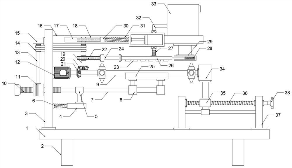
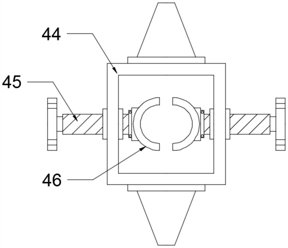
[0023] see Figure 1-4 , a surface efficient derusting device for recycling waste steel pipes, comprising a support base 1 and a steel pipe 9, a support 3 is arranged on the upper surface of the support base 1, and a top plate 16 is fixedly installed on the end of the support 3 away from the support base 1, and the support Fixtures 44 are arranged on the left and right sides above the base 1, and the drive motor 12 is arranged on the right side of the surface of the support 3. The output end of the drive motor 12 is fixedly connected to the left fixture 44, and the fixture 44 on the right is connected to the support 34 in rotation. , the steel pipe 9 is fixedly installed in the fixtures 44 on the left and right sides. In order to polish the fixed steel pipe, the output end of the drive motor 12 is fixedly connected to the bevel gear 1 21, and the bevel gear 2 20 is arranged above the bevel gear 1 21. , the second bevel gear 20 meshes with the first bevel gear 21, the top of th...

Embodiment 2

[0030] see Figure 1-6, on the basis of Example 1, in order to improve the rust removal effect, a rust remover box 33 is arranged on the right side of the upper surface of the top plate 16, and the rust remover box 33 is connected to the piston cylinder 42 through a liquid inlet pipe 32. The lower part of the piston cylinder 42 is connected to the spray chamber 26 through the telescopic hose 27, the liquid inlet pipe 32, the telescopic hose 27 and the piston cylinder 42 are all provided with a one-way valve 41, and the lower surface of the spray chamber 26 is equidistantly provided with nozzles. 23. The piston cylinder 42 is provided with a piston 40. In order to drive the piston 40 to reciprocate horizontally in the piston cylinder 42, a cavity 17 is provided in the top plate 16, and a cam-18 is provided in the cavity 17. The cam-18 The bottom of 18 is fixedly connected with the rotating shaft 19, the right side of the cam one 18 is provided with a slide seat 30, the end of t...


PUM


Abstract

The invention discloses an efficient surface rust removal device for waste steel pipe recycling, and relates to the technical field of steel pipe machining equipment. The efficient surface rust removal device comprises a supporting base and a steel pipe. Clamps are arranged above the supporting base. A drive motor is arranged on the right side of the surface of a support. The output end of the drive motor is fixedly connected with the clamp on the left side. A rotation rod and a rotation shaft are rotationally connected through a belt. The rotation rod is connected with a half gear. A push rodis arranged below the drive motor. The left side of the push rod is fixedly connected with a rack plate. The drive motor drives the clamps and the steel pipe to rotate. A grinding sand layer conductsprimary grinding on the steel pipe. A gear is engaged with the rack plate to drive a grinding sleeve on the right side and the grinding sand layer to move rightwards below the steel pipe. A limitingsleeve and a reset spring drive the grinding sleeve and the grinding sand layer to reset, and sufficient grinding on the steel pipe is achieved. A piston cylinder conveys a rust removal agent in a rust removal agent box to a spraying cavity and a sprayer, the rust removal effect is improved, manual grinding does not need to be conducted manually, and the automation degree is higher.

Description

technical field [0001] The invention relates to the technical field of steel pipe processing equipment, in particular to a surface efficient derusting device for recycling waste steel pipes. Background technique [0002] With the development of society and the improvement of building standards, steel pipes are often used as supporting materials for scaffolding and other building facilities in the construction process. Steel pipes are steel products with hollow sections whose length is much greater than the diameter or circumference. Columns are often used in buildings. Steel pipes with solid structure, the surface is easy to rust when the steel pipes are improperly placed and stored, and need to be derusted and lubricated by equipment. [0003] When recycling waste steel pipes, some steel pipes can be used directly after derusting. Usually, workers need to manually polish and derust the steel pipes. The derusting efficiency is low and wastes manpower. Contents of the inven...

Claims


Application Information

Patent Timeline
IPC IPC(8): B24B27/033B24B5/04B24B5/35C23G3/04
CPCB24B5/04B24B5/35B24B27/0092B24B27/033C23G3/04
Inventor 徐芳
Owner 徐芳
Features
  • R&D
  • Intellectual Property
  • Life Sciences
  • Materials
  • Tech Scout
  • Unparalleled Data Quality
  • Higher Quality Content
  • 60% Fewer Hallucinations
Learn More