Novel choking coil center feed double-frequency circularly polarized GPS antenna

A GPS antenna and center feeding technology, applied in the field of global satellite navigation and positioning systems, can solve problems such as reducing antenna back lobe radiation, antenna receiver multipath signal interference, enhancing antenna suppression of multipath interference, etc., to reduce back lobe, Suppresses the propagation of upper surface waves and improves the effect of front-to-back ratio and back lobe

Active Publication Date: 2021-02-19
SHANGHAI AEROSPACE ELECTRONICS CO LTD +1
View PDF5 Cites 3 Cited by
  • Summary
  • Abstract
  • Description
  • Claims
  • Application Information

AI Technical Summary

Problems solved by technology

[0004] The purpose of the present invention is to provide a new type of choke coil center feed dual-frequency circularly polarized GPS antenna to solve the technical problem of multipath signal interference

Method used


Image

  • Novel choking coil center feed double-frequency circularly polarized GPS antenna
  • Novel choking coil center feed double-frequency circularly polarized GPS antenna
  • Novel choking coil center feed double-frequency circularly polarized GPS antenna

Examples


Embodiment 1

[0043] Embodiment 1: Design of center-fed dual-frequency circularly polarized GPS antenna.

[0044] In two specific embodiments, a novel choke coil centrally fed dual-frequency circularly polarized GPS antenna operates at low frequency and high frequency. The material of the upper and lower dielectric substrates is Arlon AR 450, the relative dielectric constant is, the dielectric size G=150mm, the thicknesses are T1=0.8mm and T2=4.0mm respectively, and the distance between the upper and lower dielectric substrates is T3=4.2mm.

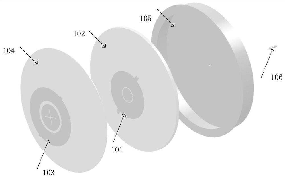
[0045] combine figure 2 with Figure 4 ~6 to describe this embodiment in detail. The upper radiation metal patch is a circular patch with tuning branches, including a cross slot patch and a ring slot patch. The outer radius of the ring slot patch is R1=35.6mm , the inner radius R2=19.4mm, the patch radius of the cross gap is R2-gap1, gap1=3.4mm, the length and width of the cross gap are A=19.4mm and B=1mm respectively, the upper layer can be realize...

Embodiment 2

[0047] Embodiment 2: Design of a novel choke coil center-fed dual-frequency circularly polarized GPS antenna.

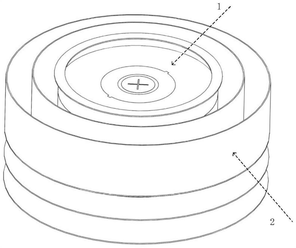
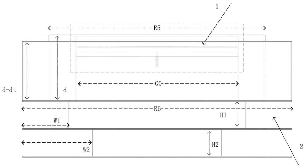
[0048] combined with figure 1 , image 3 , Figures 7 to 10 to specifically illustrate this embodiment, a new type of choke coil is placed around the center-fed dual-frequency circularly polarized GPS antenna in Example 1, and the new type of choke coil integrates 2 layers of horizontal coaxial corrugated grooves and 2 One layer of vertical radial corrugated grooves, wherein two layers of vertical radial corrugated grooves are placed below two layers of horizontal coaxial corrugated grooves, which effectively reduces the diameter of the entire choke coil. Two layers of horizontal coaxial corrugated grooves are composed of horizontal coaxial metal rings connected at the bottom. The two layers of annular choke grooves are distributed on the outer circumference of the dual-frequency antenna from the axis to the outside; the depth of the two metal rings is from the insid...


PUM

PropertyMeasurementUnit
Thicknessaaaaaaaaaa
Radiusaaaaaaaaaa
Radiusaaaaaaaaaa

Abstract

The invention discloses a novel choking coil center feed double-frequency circularly polarized GPS antenna. The antenna comprises a center feed double-frequency circularly polarized GPS antenna and anovel choking coil. Compared with an existing choking coil structure with coaxial corrugated grooves only placed in the horizontal direction, the antenna employs the novel choking coil structure; thetwo layers of longitudinal radial corrugated grooves are additionally formed in the vertical direction, the two layers of longitudinal radial corrugated grooves are placed below the two layers of horizontal coaxial corrugated grooves, and therefore the diameter of the whole choking coil is effectively reduced; the surface wave propagation on the grounding plate on the back of the antenna can be effectively inhibited, and the back lobe of the antenna is reduced, so that the front-to-back ratio and the back lobe of the antenna are improved, and the antenna is very suitable for high-precision satellite navigation and positioning systems.

Description

technical field [0001] The invention is applicable to a global satellite navigation and positioning system for ship-borne navigation, and in particular relates to a novel choke ring center-feeding dual-frequency circularly polarized GPS antenna. Background technique [0002] Global Satellite Navigation System (GNSS) is a radio navigation system based on satellite communications, mainly including the four major navigation systems of the United States GPS, China Beidou, EU Galileo and Russia Glonass, which are used in communications, disaster relief, environmental supervision, traffic safety and military defense. and other fields play an irreplaceable and important role. With the rapid development of global satellite navigation and positioning systems, the requirements for positioning precision and accuracy are getting higher and higher, but multipath interference and antenna phase center changes are two factors that cannot be ignored affecting antenna positioning. Among them...

Claims


Application Information

Patent Timeline
IPC IPC(8): H01Q1/36H01Q1/48H01Q1/52
CPCH01Q1/52H01Q1/48H01Q1/36
Inventor 孙朦朦黄志凯白旭东吕艳亭孔凡伟钱静怡熊勇华
Owner SHANGHAI AEROSPACE ELECTRONICS CO LTD
Why Eureka
Try Eureka