Use method of bone conduction sounding device

A sound-generating device and bone conduction technology, applied in bone conduction transducer hearing equipment, sensors, sensor parts, etc., can solve problems such as unsatisfactory sound effect, mid- and low-frequency response distortion, etc., to improve distortion, enrich sound effect, structure flexible effects

Active Publication Date: 2021-02-19
SUZHOU THOR ELECTRONIC TECH CO LTD
View PDF15 Cites 3 Cited by
  • Summary
  • Abstract
  • Description
  • Claims
  • Application Information

AI Technical Summary

Problems solved by technology

[0007] 2. Existing bone conduction earphones use moving iron to realize vibration conduction and pr

Method used


Image

  • Use method of bone conduction sounding device
  • Use method of bone conduction sounding device
  • Use method of bone conduction sounding device

Examples


Embodiment 1

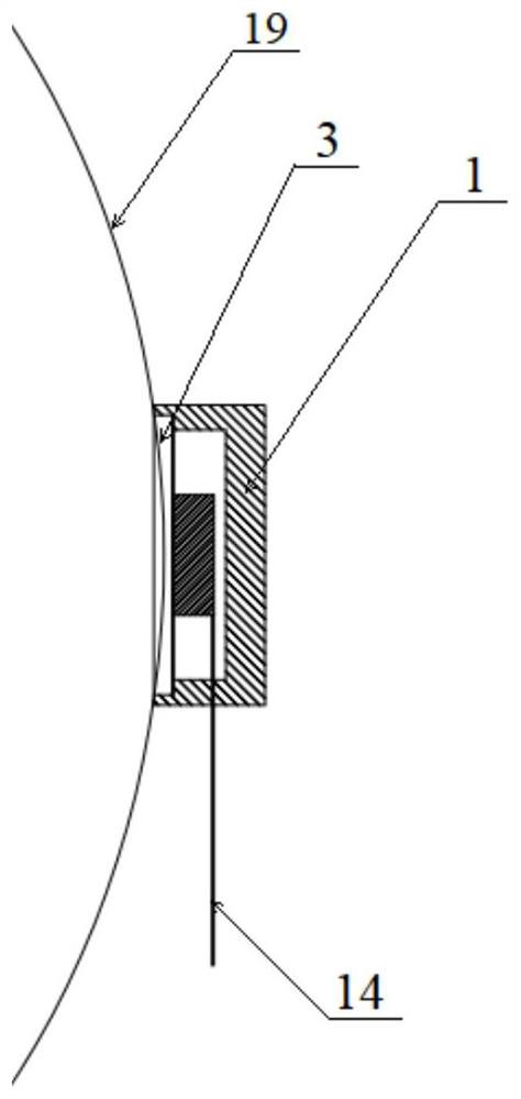
[0107] According to a specific embodiment of the present invention, in combination with the attached figure 1 , attached Figure 4 And attached Figure 7 , and the attached Figure 14 with 16 The present invention will be described in detail. In this embodiment, the bone conduction sound generating device includes a diaphragm, a bracket and an exciter. The exciter has an integrated structure. The exciter is installed on the geometric center of the effective vibration area on the inner surface of the diaphragm, and the diaphragm is circular. The multilayer structure is a solid structure combining solid materials and solid materials. In the multilayer structure, the solid materials of each layer are the same and are made of metal. Preferably, aluminum or zinc is selected, and a similar structure can also be used. For other metals with Young's modulus, the cavity surrounded by the diaphragm and the bracket is closed.

[0108] When the bone conduction sounding device is worn,...

Embodiment 2

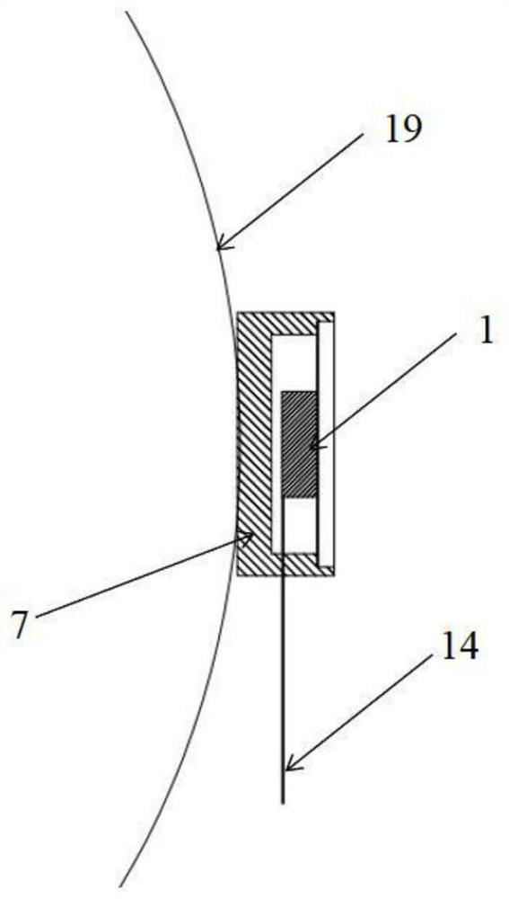
[0110] According to a specific embodiment of the present invention, in combination with the attached figure 1 , attached Image 6 And attached Figure 7 , and the attached Figure 14 , 16 and 19, the present invention is described in detail. In this embodiment, the difference between the bone conduction sounding device and Embodiment 1 is that damping holes are provided on the side wall of the bracket. ~1000hz), the size of the damping hole is 0.5mm in diameter, and the depth of the hole is 0.15mm. The working principle is similar to that of Example 1, but due to the setting of the damping hole, the diaphragm 4 and the bracket 6 are added. The damping of the air cavity makes the low-frequency frequency response significantly improved, according to the attached Figure 19 frequency response graph.

Embodiment 3

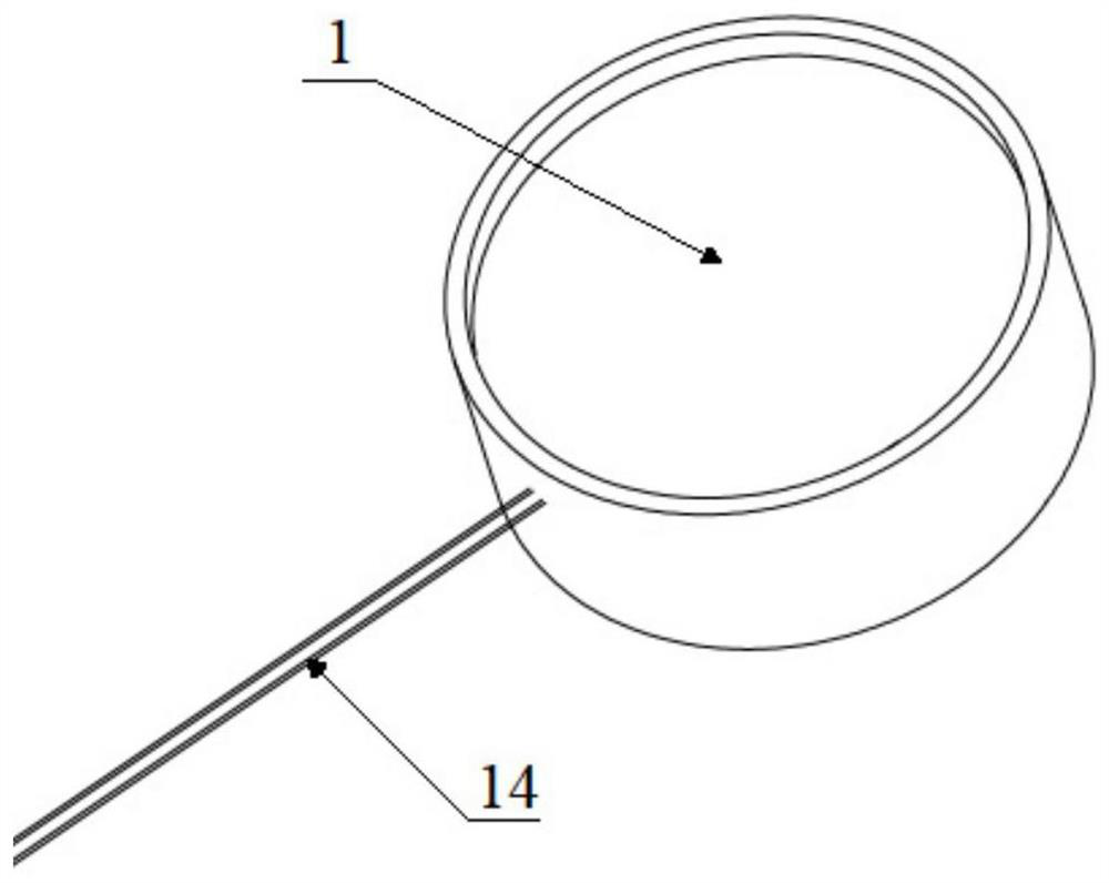
[0112] According to a specific embodiment of the present invention, in combination with the attached figure 1 , attached Image 6 And attached Figure 8 , and the attached Figure 14 , 16 and 19, the present invention is described in detail. In this embodiment, the difference between the bone conduction sounding device and Embodiment 2 is that the diaphragm is a three-layer membrane with a solid-liquid-solid structure, the liquid is located in a cavity surrounded by two layers of solid material, and the thickness of the solid material is selected to be 0.03 ~0.05mm thick aluminum film, you can also choose other similar materials with approximate Young's modulus and yield strength, the liquid is water, or other non-corrosive liquids can be used, when the bone conduction sound generating device 1 is connected to the audio player On the device, the audio playback device provides a power source for the exciter 5 in the bone conduction sound generating device 1 through a lead w...


PUM


Abstract

The invention provides a use method of a bone conduction sounding device, and belongs to the technical field of bone conduction devices. A cavity is defined by a support and a vibrating diaphragm, anexciter is arranged in the cavity, the vibrating diaphragm produces sound and vibrates under the action of the exciter, the vibrating diaphragm can be attached to a human face in the direction of thevibrating diaphragm and can also be attached to the human face in the direction of the bottom wall when the bone conduction sounding device is worn, and vibration of the vibrating diaphragm can be transmitted to the human face and then transmitted to skull and ossicle regardless of the mode, so that a person can hear the sound. The vibrating diaphragm is a single-layer or multi-layer diaphragm, and the multi-layer diaphragm comprises a plurality of combined structures. The cavity is provided with or not provided with a damping hole. The exciter comprises a magnetic circuit assembly and a coilassembly which are respectively fixed on the vibrating diaphragm and the bottom wall, and the positions of the magnetic circuit assembly and the coil assembly can be exchanged, or the exciter is integrally packaged and installed on the vibrating diaphragm. According to the method, through the use method of air coupling sound transmission or cavity wall coupling sound transmission, the middle-low frequency response effect of the bone conduction sound production device is good.

Description

technical field [0001] The invention relates to the technical field of bone conduction devices, in particular to a method for using a bone conduction sound generating device. Background technique [0002] At present, earphones on the market are divided into earphones, in-ear earphones, headsets and ear-hanging earphones according to the wearing style. Usually, most of these earphones adopt the traditional principle of using air vibration. The earphone vibrates the air, and the air vibrates the eardrum again, thereby transmitting the sound to the ear. The noise reduction function of this ordinary earphone is unsatisfactory, and the frequency and sound quality of the music that can be played are limited. At the same time, long-term use of earphones at high volume will affect the eardrum and cause hearing loss. As a result, a bone conduction earphone has gradually emerged in the market, and bone conduction wearable devices have also appeared. [0003] Bone conduction is a sou...

Claims


Application Information

Patent Timeline
IPC IPC(8): H04R7/04H04R7/08H04R1/10
CPCH04R7/04H04R7/08H04R1/1091H04R2460/13
Inventor 曹洪斌赵玉洗沈佳龙
Owner SUZHOU THOR ELECTRONIC TECH CO LTD
Why Eureka
Try Eureka